
Understanding Optocoupler Relays: A Comprehensive Guide
Relays play a crucial role in electrical circuits, offering a means to control high-power devices using low-power signals. Among various types of relays, optocoupler relays stand out for their ability to provide electrical isolation. In this guide, we will delve into the basics of relays, their types, and a detailed exploration of optocoupler relays.
What is a Relay?
A relay is an electrically operated switch that uses an electromagnet to mechanically control a circuit. It consists of three main terminals:
- NC (Normally Closed)
- NO (Normally Open)
- COM (Common Terminal)
When the relay coil is not activated, the relay acts as an open circuit. However, upon activation, the relay completes the circuit, allowing current to flow.
Applications of Relays
- Used in high-power devices for switching applications.
- Applied in AC motors for transitioning between star and delta connections.
- Functions as a protective device, such as a Buchholz relay in transformers to detect faults.
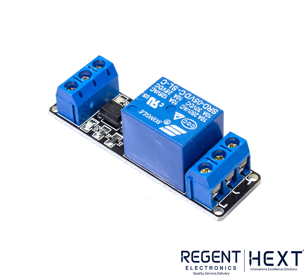
Understanding Optocoupler Relays
An optocoupler relay is a type of relay that operates based on opto-isolation technology, ensuring no direct electrical connection between the controlling and controlled circuits. This isolation protects the controller from high voltage fluctuations.
Components of an Optocoupler Relay
- Relay: Acts as the switching mechanism.
- Opto-isolator: Facilitates signal transmission without physical connection.
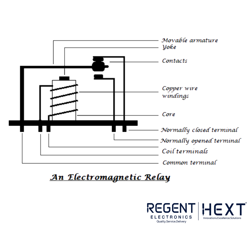
Relay Pinout and Construction
A standard relay consists of:
- NO (Normally Open) Terminal – Connected when the relay is activated.
- NC (Normally Closed) Terminal – Connected when the relay is inactive.
- COM (Common Terminal) – Moves between NC and NO based on activation.
When the electromagnet inside the relay is energized, it generates a magnetic flux, attracting the armature and changing its position from NC to NO.
Solid-State Relays (SSR)
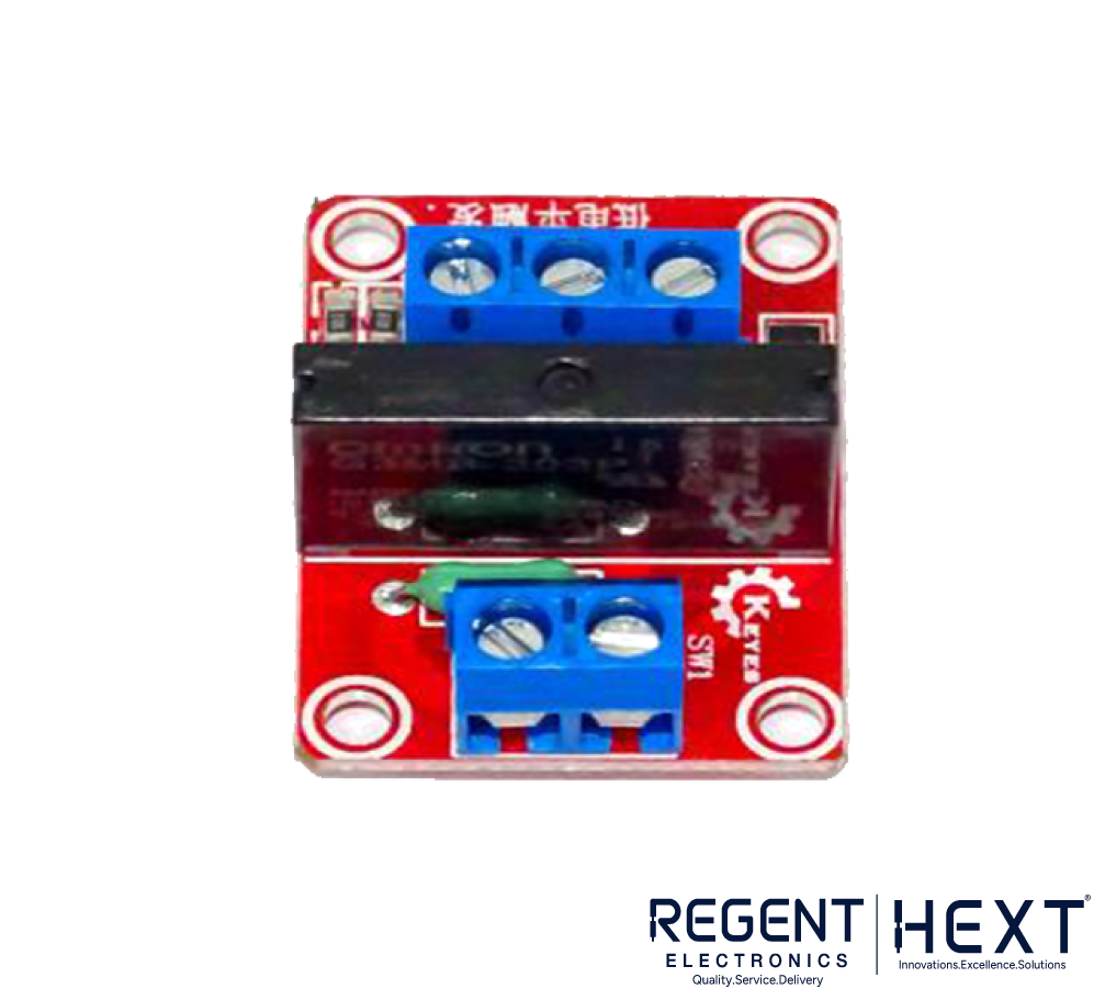
Unlike conventional relays, solid-state relays (SSRs) utilize thyristors or transistors for switching, enabling faster operation and enhanced durability. SSRs offer superior performance in high-speed applications and will be discussed in further detail in a future guide.
Understanding Opto-Isolators
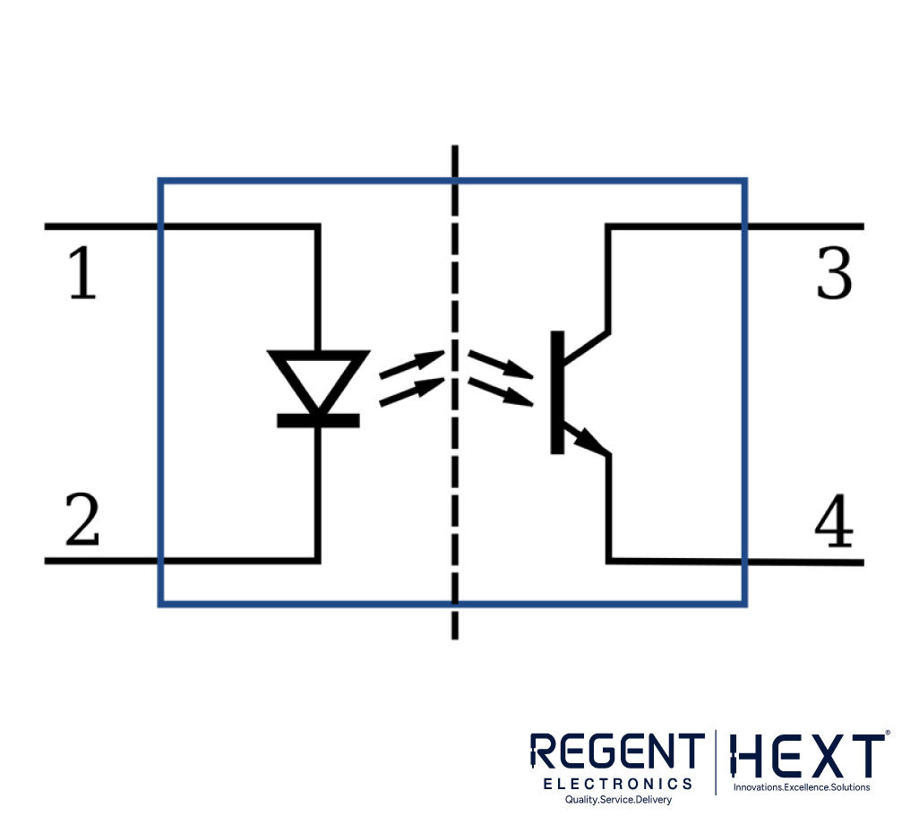
Opto-isolators, also known as optocouplers, are electronic components that provide isolation between input and output signals using light. They consist of:
- LED (Light Emitting Diode) – Generates light when current passes through it.
- Phototransistor – Responds to the LED’s light to switch circuits.
Working of an Optocoupler
When the LED is off, the phototransistor remains in an open state. Upon activation of the LED, light falls on the transistor’s base, causing it to switch to a closed state. The greater the intensity of light, the more electrons flow through the transistor, ensuring efficient circuit operation.
Optocoupler Relay Circuit with Arduino
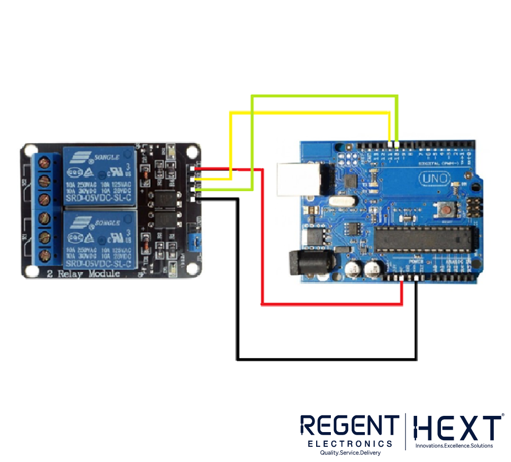
Optocoupler relays can be integrated with microcontrollers such as Arduino and STM. Below is a simple Arduino code for controlling a relay using an optocoupler:
int D1 = 11; // Define the pin connected to the relay
void setup() {
pinMode(D1, OUTPUT); // Set the pin as an output
}
void loop() {
digitalWrite(D1, HIGH); // Activate the relay
delay(1000); // Wait for one second
digitalWrite(D1, LOW); // Deactivate the relay
delay(1000); // Wait for one second
}
Conclusion
Optocoupler relays provide an efficient way to control high-power devices while ensuring electrical isolation. Their ability to safeguard controllers from high voltage makes them an ideal choice for various applications in automation, power electronics, and industrial control systems. For a wide range of relays, visit Regent Electronics to explore high-quality relay solutions.