
Interfacing GPS Module with Arduino and Raspberry Pi
This guide will help you set up the GPS module with Arduino as well as Raspberry Pi.
Introduction
This article demonstrates the interfacing of the UBlox NEO-M8N GPS module with Arduino Uno and Raspberry Pi. It is a widely used, cost-effective, and high-performance GPS module. This GPS module features a ceramic patch antenna, an onboard memory chip, and a backup battery, making it easily integrable with various microcontrollers.
GPS Interfacing with Arduino Uno
We are using the U-Blox NEO-M8N GPS module to interface with the Arduino Uno microcontroller.
Pin Configuration:
The GPS module operates on the RS232 serial protocol with four pins:
- VCC: Power supply
- GND: Ground
- TX: Transmit data
- RX: Receive data
The module continuously transmits NMEA data strings via the TX pin. NMEA (National Marine Electronics Association) is a standard text protocol used by all GPS devices.
Connection Diagram
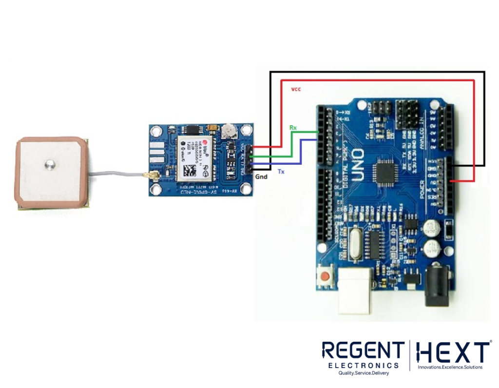
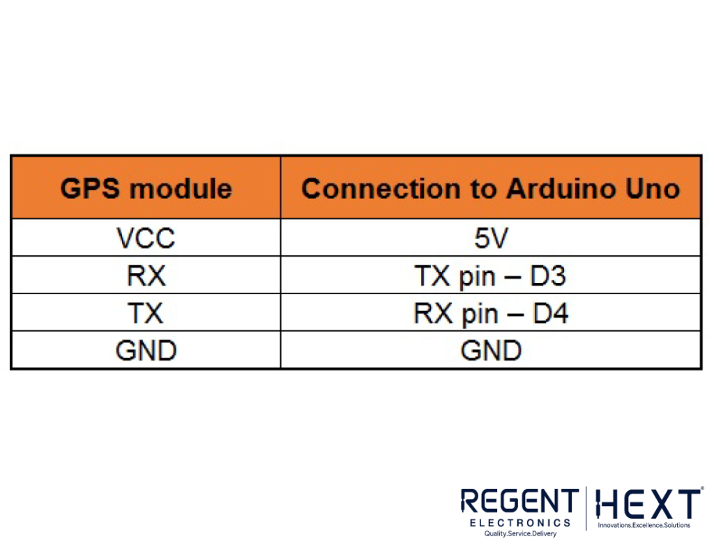
In Arduino, we assign the TX pin to D3 and the RX pin to D4. Connect the module as follows:
- GPS VCC → Arduino 5V
- GPS GND → Arduino GND
- GPS TX → Arduino D3
- GPS RX → Arduino D4
Required Software:
- Arduino IDE
- Software Serial Library
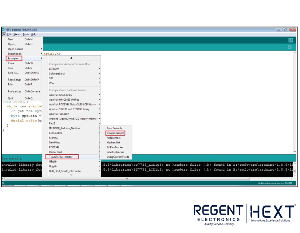
- TinyGPS Library for Arduino (Optional)
Arduino Code:
#include <SoftwareSerial.h>
static const int RXPin = 4, TXPin = 3;
static const uint32_t GPSBaud = 9600;
SoftwareSerial ss(RXPin, TXPin);
void setup() {
Serial.begin(115200);
ss.begin(GPSBaud);
}
void loop() {
while (ss.available() > 0) {
Serial.write(ss.read());
}
}
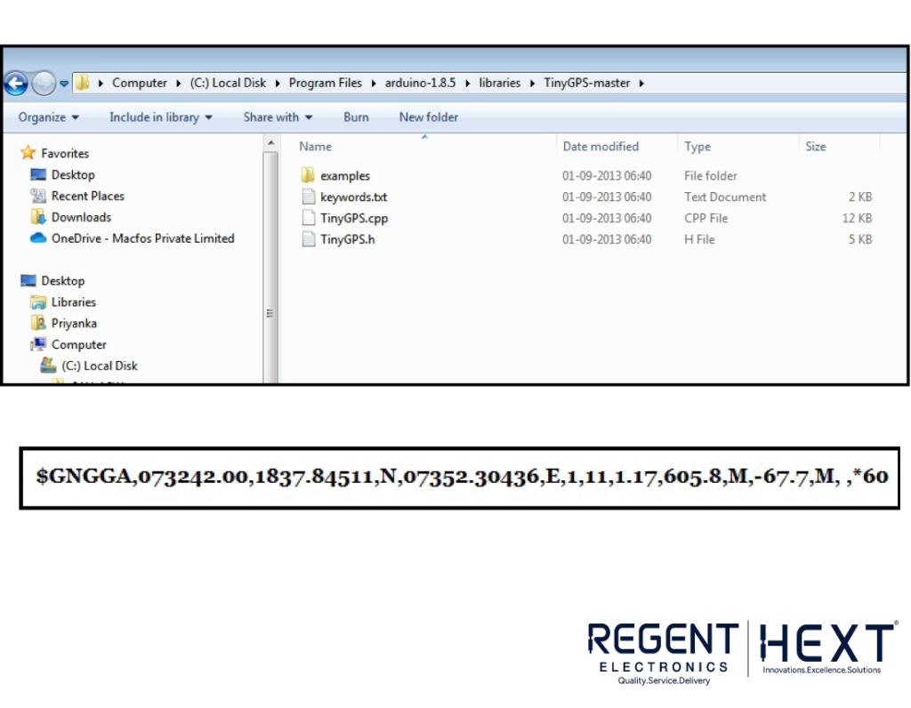
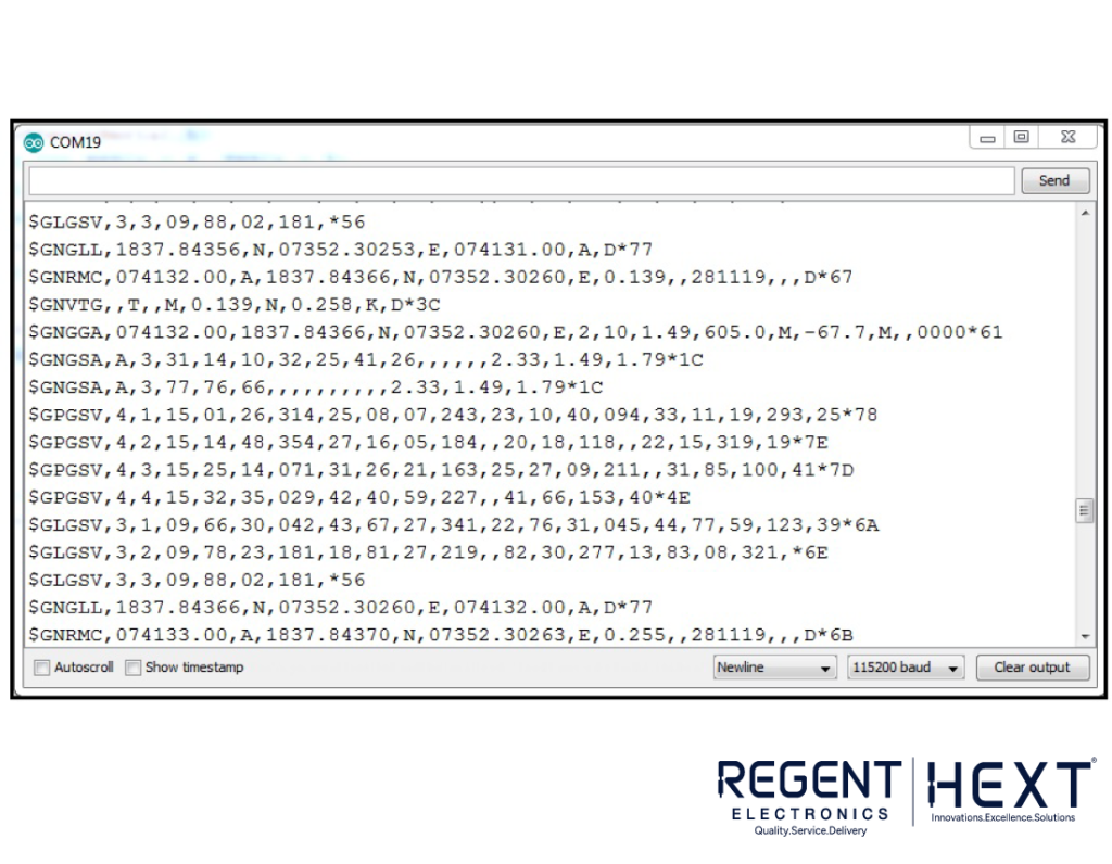
NMEA Data Interpretation
Different types of NMEA sentences provide various types of data. A typical $GNGGA message includes:
- Time Stamp: UTC time of the position fix
- Latitude & Longitude: Geographical coordinates
- Fix Quality: Indicates GPS signal validity
- Number of Satellites: Active satellites in use
- Altitude: Height above sea level
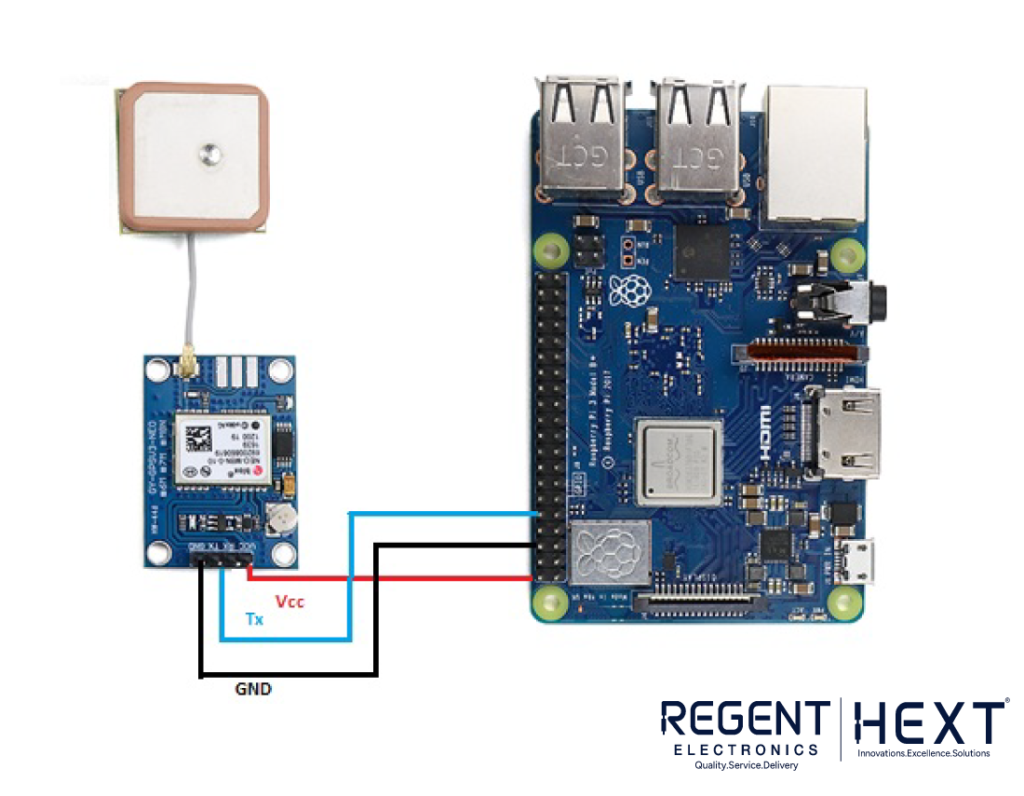
GPS Interfacing with Raspberry Pi
We will now interface the U-Blox NEO-M8N GPS module with Raspberry Pi using Python.
Steps to Configure Raspberry Pi
Step 1: Setting up UART
Run the following command to edit the boot configuration:
sudo nano /boot/config.txt
Add these lines at the bottom:
dtparam=spi=on
dtoverlay=pi3-disable-bt
core_freq=250
enable_uart=1
force_turbo=1
Save and exit, then reboot:
sudo reboot
Step 2: Disable Serial Getty Service
Find the serial port using:
ls -l /dev
If Serial0 is linked with ttyAMA0, disable it:
sudo systemctl stop serial-getty@ttyAMA0.service
sudo systemctl disable serial-getty@ttyAMA0.service
If Serial0 is linked with ttys0, disable it:
sudo systemctl stop serial-getty@ttys0.service
sudo systemctl disable serial-getty@ttys0.service
Reboot the system:
sudo reboot
Step 3: Enable ttys0
sudo systemctl enable serial-getty@ttys0.service
Step 4: Install Required Libraries
sudo apt-get install minicom
sudo pip install pynmea2
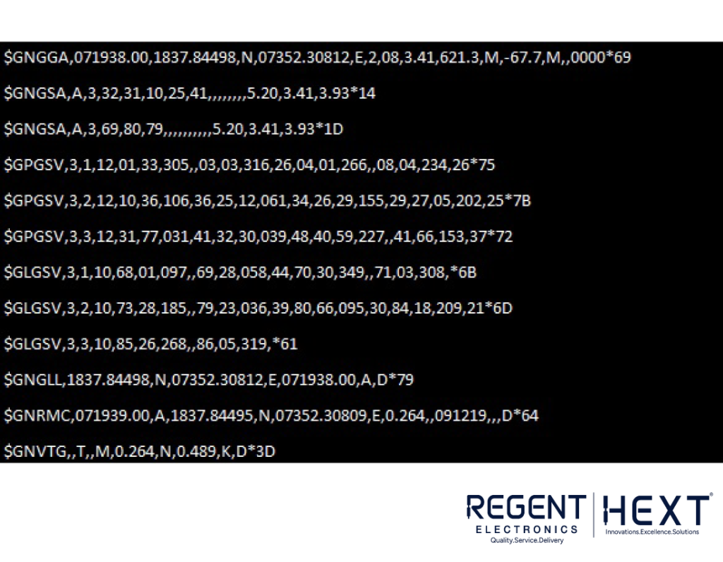
Step 5: Testing GPS Output
Ensure the GPS module is blinking, then run:
sudo cat /dev/ttyAMA0
Python Code for GPS Module
import serial
import pynmea2
port = “/dev/ttyAMA0”
ser = serial.Serial(port, baudrate=9600, timeout=0.5)
while True:
newdata = ser.readline()
if newdata[0:6] == “$GPRMC”:
newmsg = pynmea2.parse(newdata.decode(‘utf-8’))
lat = newmsg.latitude
lng = newmsg.longitude
gps = f”Latitude={lat} and Longitude={lng}”
print(gps)
Output
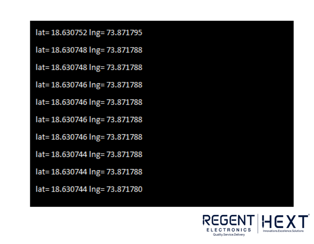
The final output will display real-time latitude and longitude, helping in precise location tracking.
Conclusion
By interfacing the GPS module with both Arduino and Raspberry Pi, we can retrieve accurate location data. This module can be used for live GPS tracking systems, navigation devices, and automation projects. Stay tuned for more such tutorials from Regent Electronics!