

Sound Sensor Basics: Pin Configuration, Working, Applications, and Interfacing
In today’s automated world, sound sensors play a crucial role in enabling voice-activated and sound-responsive systems. Whether for home automation, security systems, or robotics, sound sensors provide an efficient way to detect and respond to audio signals. In this article, we will explore the fundamentals of sound sensors, their working principles, pin configurations, and their interfacing with Arduino.
What is a Sound Sensor?
A sound sensor is an electronic device designed to detect sound waves and convert them into electrical signals. Sound is essentially a waveform of energy produced through mechanical vibrations, with different frequencies defining different types of sounds. A sound sensor captures these vibrations and translates them into a measurable electrical output.
Pin Configuration and Components
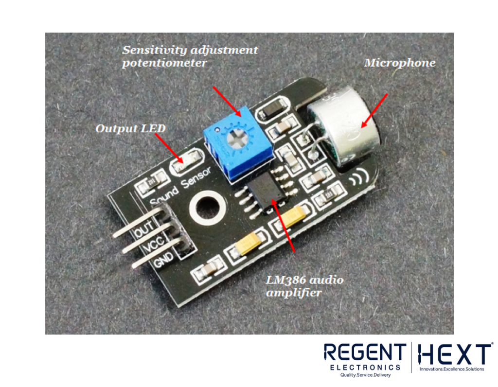
A sound sensor module consists of the following components:
- Microphone – Acts as a transducer to detect sound
- Potentiometer – Adjusts the sensitivity of sound detection
- LM386 Low Power Audio Amplifier – Amplifies the detected sound signals
- LED Indicator – Provides visual feedback on sound detection
- Resistors & Capacitors – Passive components for circuit stability
Pin Configuration:
- VCC – Power supply (3.3V to 5V DC)
- GND – Ground connection
- OUT – Digital output pin, provides HIGH when no sound is detected and LOW when sound is detected
A potentiometer allows users to set a threshold value for sound detection. When the detected sound surpasses this threshold, the module outputs a LOW signal.
Working Principle of a Sound Sensor
The working of a sound sensor is similar to the human ear. Just as our ears convert vibrations into electrical signals via the auditory system, a sound sensor captures sound vibrations and converts them into electrical signals using a microphone.
The microphone consists of a diaphragm surrounded by a coil and a magnet. When sound waves hit the diaphragm, it vibrates, causing the coil to move relative to the magnet, which induces a current. This current is then amplified and processed for further use.
Interfacing Sound Sensor with Arduino Uno
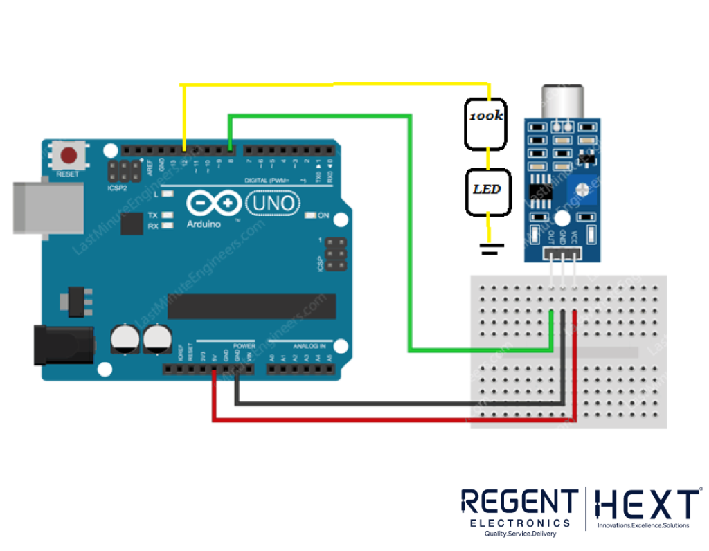
Connecting a sound sensor with an Arduino Uno is straightforward. Here’s how to make the connections:
- VCC → Connect to 5V on Arduino
- GND → Connect to GND on Arduino
- OUT → Connect to digital pin D8 on Arduino
To indicate the output, connect an LED with a 100k resistor to pin D12 on the Arduino.
Arduino Code for Sound Detection:
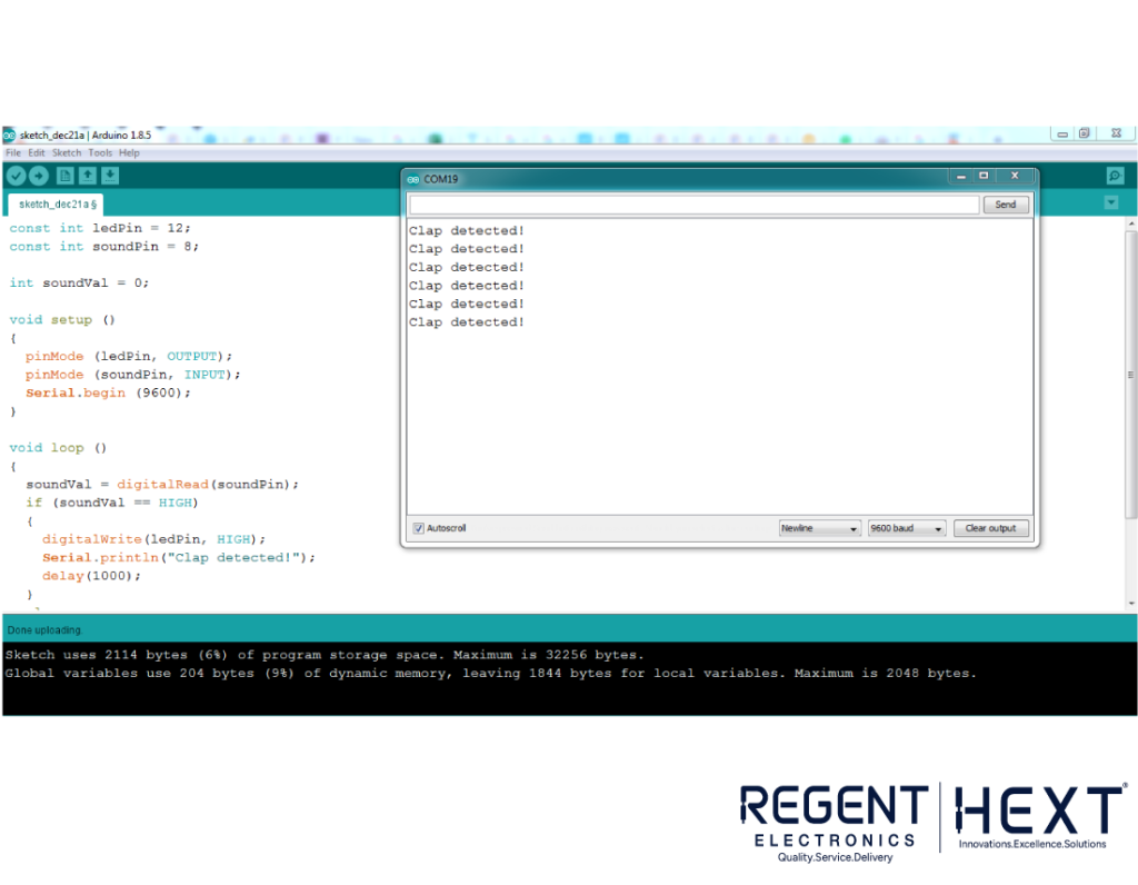
const int ledPin = 12;
const int soundPin = 8;
int soundVal = 0;
void setup() {
pinMode(ledPin, OUTPUT);
pinMode(soundPin, INPUT);
Serial.begin(9600);
}
void loop() {
soundVal = digitalRead(soundPin);
if (soundVal == HIGH) {
digitalWrite(ledPin, HIGH);
Serial.println(“Clap detected”);
delay(1000);
} else {
digitalWrite(ledPin, LOW);
}
}
This code detects a clap sound and turns on an LED accordingly. The detected event is also displayed in the Arduino Serial Monitor.
Applications of Sound Sensors
Sound sensors have numerous applications, including:
- Home and Office Security Systems – Detect unauthorized entry based on sound
- Spy Circuits – Used in covert surveillance
- Home Automation – Enables voice-activated appliances
- Robotics – Integrates sound recognition for smart robots
- Smartphones – Assists in voice recognition features
- Ambient Sound Recognition – Helps in noise level monitoring
- Audio Amplifiers – Used in sound processing circuits
- Sound Level Recognition – Measures environmental noise levels
Conclusion
Sound sensors provide a convenient and efficient way to detect and process sound for automation and security applications. This article covered the fundamental working, pin configuration, interfacing with Arduino, and real-world applications of sound sensors. Whether you’re a hobbyist or an engineer, incorporating sound sensors into your projects can significantly enhance their functionality.
Stay tuned for more insightful guides on sensors and automation. Keep learning and innovating!