

DIY Arduino-Based Digital Password Lock System by Regent Electronics
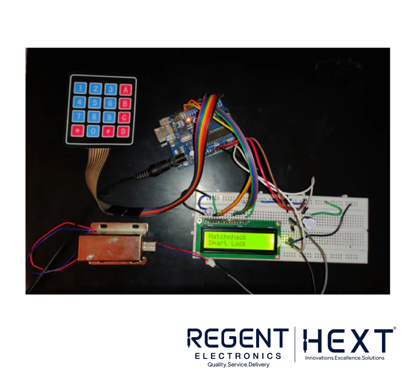
Looking for an innovative project that combines security with creativity? Build your own keyless digital password lock system using Arduino! This comprehensive guide will help you create a passcode-protected lock system featuring a 4×4 keypad, a 16×2 LCD display, and a solenoid electromagnetic lock. Ideal for doors, secret boxes, or even piggy banks, this DIY project is both functional and rewarding.
Components You’ll Need
- Arduino Board
- 16×2 LCD Display
- 4×4 Matrix Keypad
- Buzzer
- 10k Potentiometer
- 560-ohm Resistor
- Electromagnetic Lock
- Connecting Wires
- Power Supply
- BC547 Transistor
- 1N4007 Diode
What Is a 4×4 Matrix Keypad?
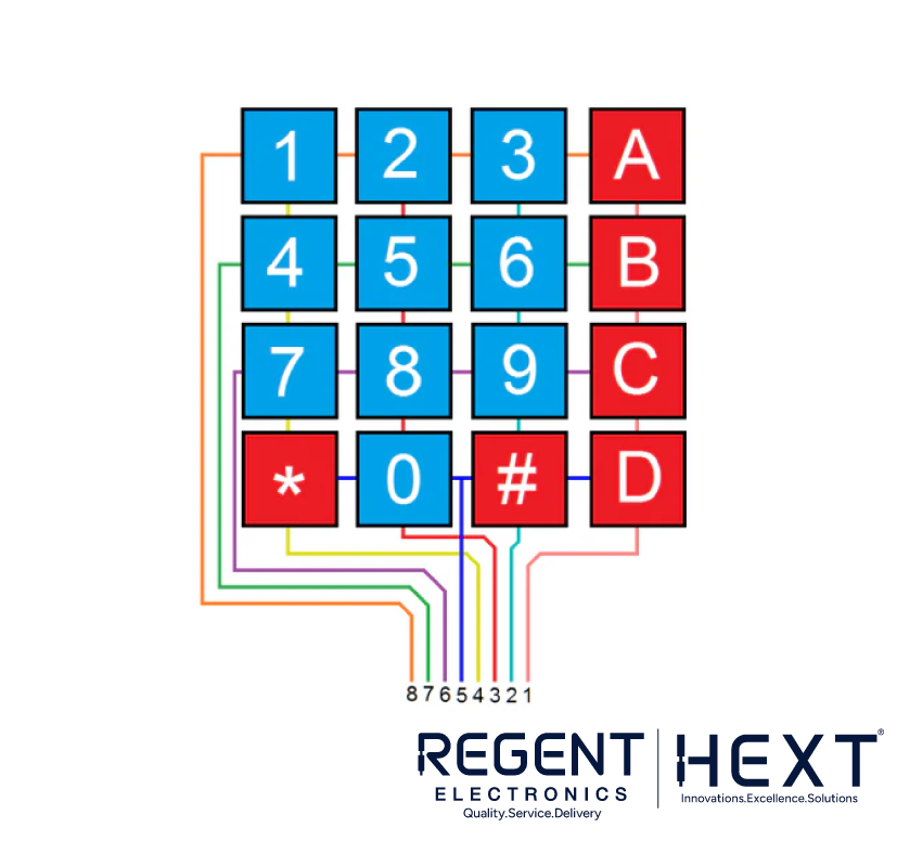
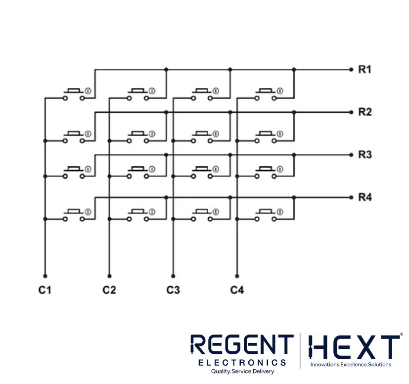
The 4×4 keypad is a grid of switches arranged in rows and columns. When you press a key, it establishes a connection between a specific row and column, which the microcontroller detects.
How It Works
- Rows are grounded sequentially by the microcontroller.
- Columns are scanned to check for connections.
- The microcontroller identifies the pressed key based on the row and column where the connection occurs.
This method ensures efficient and accurate detection of key presses.
Interfacing a 16×2 LCD with Arduino
The 16×2 LCD display is essential for showing passcode inputs, system messages, and feedback. For this project, the LCD operates in 4-bit mode, using fewer data lines for a simplified connection.
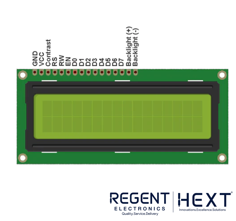
Pinout of the LCD
- Pin 1 (Vss): Ground.
- Pin 2 (Vcc): +5V supply.
- Pin 3 (VEE): Contrast adjustment via a potentiometer.
- Pin 4 (RS): Register select (data/command mode).
- Pin 5 (R/W): Read/Write mode.
- Pin 6 (E): Enable pin.
- Pins 7-14 (DB0-DB7): Data pins.
- Pin 15 (Backlight +): Backlight anode.
- Pin 16 (Backlight -): Backlight cathode.
How a Solenoid Lock Works
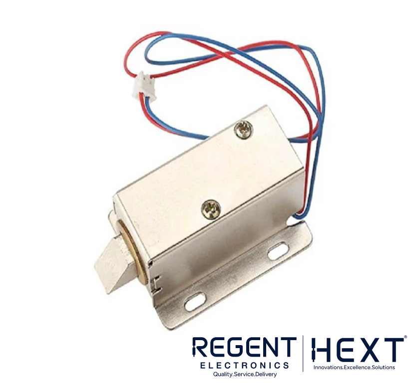
A solenoid lock uses an electromagnet to move a plunger, either securing the strike opening or allowing it to release. When powered, the lock either opens or remains closed, depending on the configuration.
Circuit Diagram
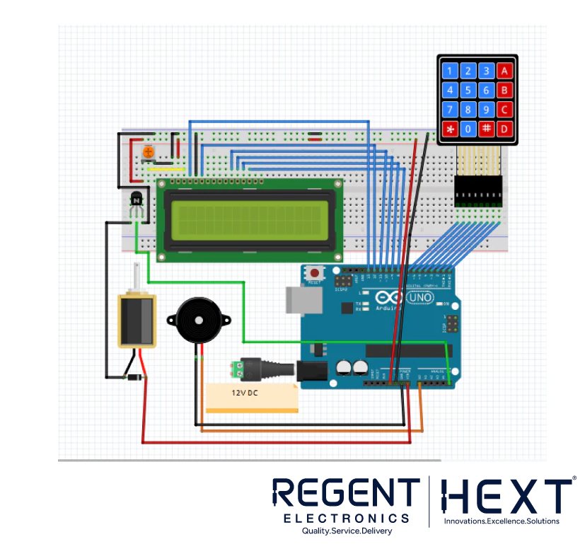
To build the system, connect the following:
- The 4×4 keypad to the Arduino’s digital pins.
- The LCD display to its respective pins on the Arduino.
- The solenoid lock through a BC547 transistor and a 1N4007 diode for proper operation.
- Power connections for the lock and Arduino.
Arduino Code
Here’s the complete code to program your digital password lock system.
cpp
CopyEdit
#include <Keypad.h>
#include <LiquidCrystal.h>
#include <EEPROM.h>
LiquidCrystal lcd(13, 12, 11, 10, 9, 8);
char password[4];
char pass[4], pass1[4];
int i = 0;
int buzzer = A0;
int Relay = A5;
char customKey = 0;
const byte ROWS = 4;
const byte COLS = 4;
char hexaKeys[ROWS][COLS] = {
{‘1’, ‘2’, ‘3’, ‘A’},
{‘4’, ‘5’, ‘6’, ‘B’},
{‘7’, ‘8’, ‘9’, ‘C’},
{‘*’, ‘0’, ‘#’, ‘D’}
};
byte rowPins[ROWS] = {7, 6, 5, 4};
byte colPins[COLS] = {3, 2, 1, 0};
Keypad customKeypad = Keypad(makeKeymap(hexaKeys), rowPins, colPins, ROWS, COLS);
void setup() {
pinMode(Relay, OUTPUT);
pinMode(buzzer, OUTPUT);
lcd.begin(16, 2);
lcd.print(“Smart Lock”);
delay(2000);
lcd.clear();
lcd.print(“Enter Passcode:”);
for (int j = 0; j < 4; j++) {
pass[j] = EEPROM.read(j);
}
}
void loop() {
customKey = customKeypad.getKey();
if (customKey) {
password[i++] = customKey;
lcd.print(“*”);
if (i == 4) {
i = 0;
if (strncmp(password, pass, 4) == 0) {
lcd.clear();
lcd.print(“Access Granted”);
digitalWrite(Relay, HIGH);
delay(5000);
digitalWrite(Relay, LOW);
lcd.clear();
lcd.print(“Enter Passcode:”);
} else {
lcd.clear();
lcd.print(“Access Denied”);
digitalWrite(buzzer, HIGH);
delay(1000);
digitalWrite(buzzer, LOW);
lcd.clear();
lcd.print(“Enter Passcode:”);
}
}
}
}
Applications
- Home Security: Secure doors and cabinets.
- DIY Projects: Secret boxes, safes, or lockers.
- Educational Tools: Learn and teach Arduino programming.
Why Choose Regent Electronics?
Regent Electronics offers high-quality components and expert guidance for your DIY projects. Whether you’re a hobbyist or a professional, we provide everything you need for innovative electronics projects.
Shop now to get started on your digital password lock system!