
DIY Boost Converter Using the MC34063 IC – A Step-by-Step Guide
Looking to design your own boost converter? You’re in the right place! In this guide, we’ll explore how to create a 5V to 12V boost converter using the versatile MC34063 IC, which is perfect for DC-to-DC conversions. Whether you’re a beginner or an enthusiast, this project is simple yet efficient. Let’s dive in!
Introduction to the MC34063 IC
The MC34063 is a widely-used DC-to-DC converter IC, capable of working as both a step-down (buck) and step-up (boost) converter. It comes in an 8-pin DIP package and offers several features that make it ideal for voltage conversion projects. With a switching frequency of up to 100 kHz, it supports various applications like voltage regulation, battery chargers, and power supplies.
Key Features of the MC34063 IC
- Built-in oscillator and comparator for efficient operation.
- Adjustable output voltage with minimal external components.
- Handles input voltage from 3V to 40V.
- Supports a peak current output of up to 1.5A.
- Built-in short-circuit protection and low standby current.
- Suitable for applications like telecommunications, medical devices, and more.
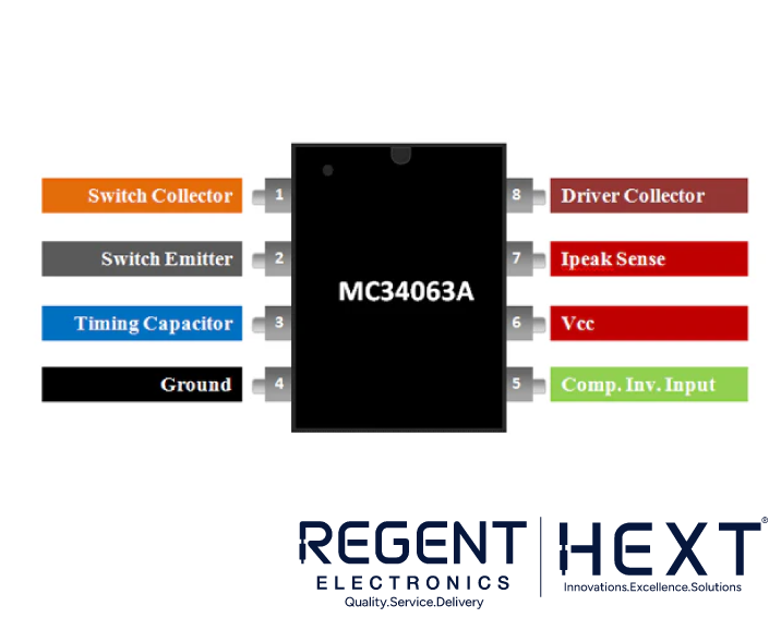
Pin Configuration of MC34063 IC

| Pin Number | Pin Name | Description |
| 1 | Switch Collector | Output voltage pin (transistor collector). |
| 2 | Switch Emitter | Emitter pin of the internal transistor. |
| 3 | Timing Capacitor | Controls the switching frequency. |
| 4 | Ground | Connects to the negative terminal of supply. |
| 5 | Comparator Inverting Input | Sets output voltage. |
| 6 | VCC | Input voltage pin. |
| 7 | Ipeak Sense | Sets the peak output current. |
| 8 | Driver Collector | Collector pin for the switching transistor. |
Why Choose the MC34063 for DC-to-DC Conversion?
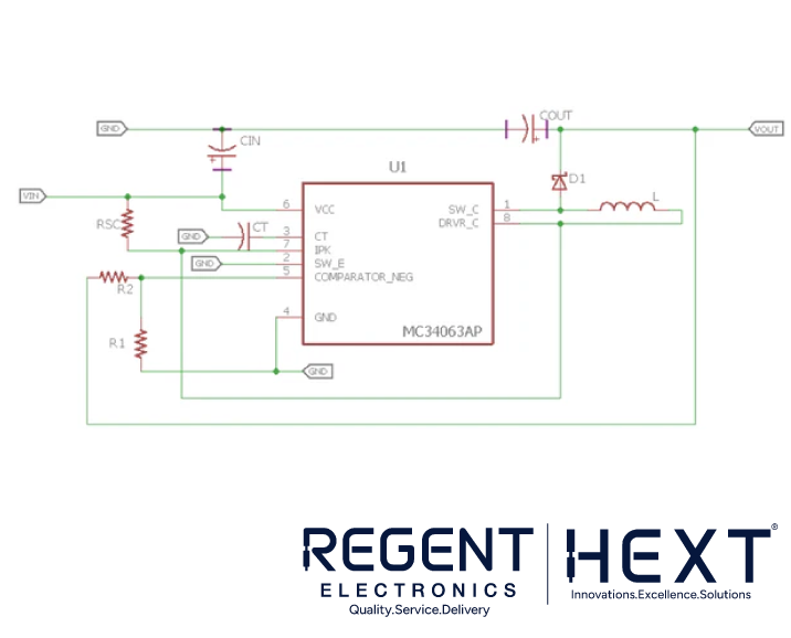
The MC34063 can be used in buck, boost, and inverting topologies with minimal external components. In this project, we’ll focus on building a boost converter that steps up 5V input to 12V output. The circuit is cost-effective and provides high efficiency, making it ideal for DIY electronics projects.
Step-by-Step Guide to Building the Boost Converter
Step 1: Select the Schottky Diode
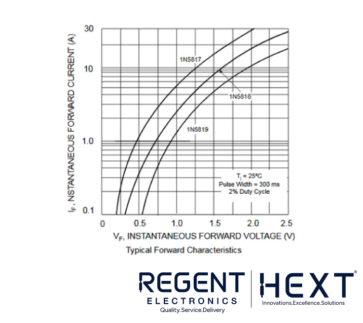
Use the 1N5819 Schottky diode, which has a low forward voltage drop of 0.49V at 1A current. This ensures better efficiency in high-frequency applications.
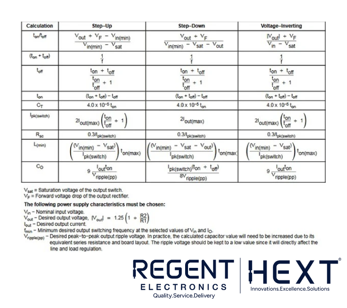
Step 2: Calculate Ton/Toff
Using the formula:
Ton/Toff=Vout+Vf−Vin (min)Vin (min)−Vsat\text{Ton/Toff} = \frac{V_{\text{out}} + V_f – V_{\text{in (min)}}}{V_{\text{in (min)}} – V_{\text{sat}}}Ton/Toff=Vin (min)−VsatVout+Vf−Vin (min)
For:
- Vout=12VV_{\text{out}} = 12VVout=12V
- Vf=0.49VV_f = 0.49VVf=0.49V
- Vin (min)=4.5VV_{\text{in (min)}} = 4.5VVin (min)=4.5V
- Vsat=0.45VV_{\text{sat}} = 0.45VVsat=0.45V
Ton/Toff=12+0.49−4.54.5−0.45=1.97\text{Ton/Toff} = \frac{12 + 0.49 – 4.5}{4.5 – 0.45} = 1.97Ton/Toff=4.5−0.4512+0.49−4.5=1.97
Step 3: Calculate Ton + Toff
The switching frequency is set at 50kHz (from the datasheet).
Ton + Toff=1f=150,000=20 μs\text{Ton + Toff} = \frac{1}{f} = \frac{1}{50,000} = 20 \, \mu sTon + Toff=f1=50,0001=20μs
Step 4: Calculate Toff
Using:
Toff=Ton + Toff(Ton/Toff)+1\text{Toff} = \frac{\text{Ton + Toff}}{(\text{Ton/Toff}) + 1}Toff=(Ton/Toff)+1Ton + Toff Toff=20 μs1.97+1=6.73 μs\text{Toff} = \frac{20 \, \mu s}{1.97 + 1} = 6.73 \, \mu sToff=1.97+120μs=6.73μs
Step 5: Calculate Ton
Ton=(Ton + Toff)−Toff=20 μs−6.73 μs=13.27 μs\text{Ton} = (\text{Ton + Toff}) – \text{Toff} = 20 \, \mu s – 6.73 \, \mu s = 13.27 \, \mu sTon=(Ton + Toff)−Toff=20μs−6.73μs=13.27μs
Step 6: Choose the Timing Capacitor (Ct)
Using:
Ct=4.0×10⁻⁵×TonC_t = 4.0 \times 10^{-5} \times \text{Ton}Ct=4.0×10⁻⁵×Ton Ct=4.0×10−5×13.27 μs=530.8 pFC_t = 4.0 \times 10^{-5} \times 13.27 \, \mu s = 530.8 \, pFCt=4.0×10−5×13.27μs=530.8pF
A 560pF ceramic capacitor is a suitable choice.
Step 7: Calculate Peak Current (Ipk)
Ipk=2×Iout (max)×(Ton/Toff+1)I_{\text{pk}} = 2 \times I_{\text{out (max)}} \times (\text{Ton/Toff} + 1)Ipk=2×Iout (max)×(Ton/Toff+1)
For Iout (max)=200mAI_{\text{out (max)}} = 200mAIout (max)=200mA:
Ipk=2×0.2×(1.97+1)=1.2AI_{\text{pk}} = 2 \times 0.2 \times (1.97 + 1) = 1.2AIpk=2×0.2×(1.97+1)=1.2A
Step 8: Determine Sense Resistor (Rsc)
Rsc=0.3IpkR_{\text{sc}} = \frac{0.3}{I_{\text{pk}}}Rsc=Ipk0.3 Rsc=0.31.2=0.25 ΩR_{\text{sc}} = \frac{0.3}{1.2} = 0.25 \, \OmegaRsc=1.20.3=0.25Ω
Step 9: Calculate Inductor Value (Lmin)
Lmin=(Vin (min)−Vsat)Ipk×TonL_{\text{min}} = \frac{(V_{\text{in (min)}} – V_{\text{sat}})}{I_{\text{pk}}} \times \text{Ton}Lmin=Ipk(Vin (min)−Vsat)×Ton Lmin=4.5−0.451.2×13.27 μs=44.8 μHL_{\text{min}} = \frac{4.5 – 0.45}{1.2} \times 13.27 \, \mu s = 44.8 \, \mu HLmin=1.24.5−0.45×13.27μs=44.8μH
Choose a 45µH inductor.
Step 10: Calculate Output Capacitor (Cout)
For a ripple of 200mV peak-to-peak:
Cout=9×(Ripple×TonRipple Voltage)C_{\text{out}} = 9 \times \left(\frac{\text{Ripple} \times \text{Ton}}{\text{Ripple Voltage}}\right)Cout=9×(Ripple VoltageRipple×Ton) Cout=9×(0.2×13.27 μs0.2)=119.43 μFC_{\text{out}} = 9 \times \left(\frac{0.2 \times 13.27 \, \mu s}{0.2}\right) = 119.43 \, \mu FCout=9×(0.20.2×13.27μs)=119.43μF
Use a 120µF 20V capacitor for better ripple reduction.
Step 11: Feedback Resistor Selection
The output voltage formula is:
Vout=1.25×(1+R2R1)V_{\text{out}} = 1.25 \times \left(1 + \frac{R_2}{R_1}\right)Vout=1.25×(1+R1R2)
For Vout=12VV_{\text{out}} = 12VVout=12V, choose R1=910 ΩR_1 = 910 \, \OmegaR1=910Ω and R2=8.2 kΩR_2 = 8.2 \, k\OmegaR2=8.2kΩ.
Conclusion
By following these steps and using the calculated values, you can design an efficient 5V to 12V boost converter. The MC34063 IC is a versatile and reliable choice for such projects. Get started with your DIY project today and explore the world of electronics with Regent Electronics!