
DIY TV Remote Controlled Home Automation System – An Innovative Arduino Project for Home Control
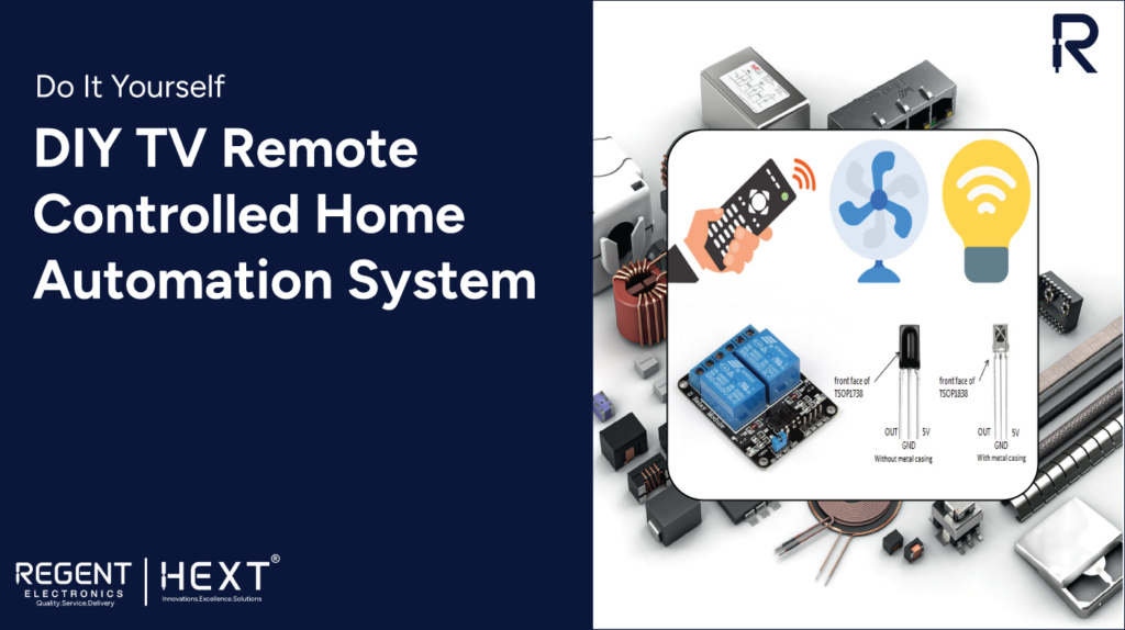
Welcome to this exciting tutorial where we explore creating your own DIY home automation system controlled by your TV or DVD IR remote! By interfacing an IR receiver (TSOP1838) with an Arduino board, you’ll learn how to control home appliances like a fan or bulb using a Relay Module. This step-by-step guide will show you how to leverage everyday objects, such as your remote, to automate your home environment.
Components Required for the Project:
- Arduino Board
- TSOP1838 IR Receiver or TSOP1738
- 5V Two-Channel Relay Module
- Connecting Wires
- Power Supply
- TV/DVD/MP3 IR Remote
- Bulb with Holder
- Breadboard
What is the TSOP1838 / TSOP1738 IR Receiver?


The TSOP1838 is a widely used IR receiver that works by receiving infrared signals transmitted by a remote control. It works specifically with signals at 38kHz frequency, making it ideal for communication with devices like TVs, DVD players, and other appliances. The TSOP1738 is a slightly older model but operates similarly. Both models are perfect for building your own home automation system with Arduino.
Pinout Description:
- GND: Ground pin for establishing a common ground with other devices.
- VSS/DC 5V: Power input for activating the internal decoder and IR receiver.
- Output: This pin sends output as a voltage signal when the device receives an IR signal.
TSOP1838 Features:
- Compact and Efficient: Includes a photodetector and amplifier in one package.
- Low Power Consumption: Only uses power during operation.
- Compatibility: Works with TTL/CMOS microcontrollers and ICs.
- Enhanced Performance: Excellent shielding against electrical disturbances and ambient light.
How to Interface the Two-Channel Relay Module with Arduino?
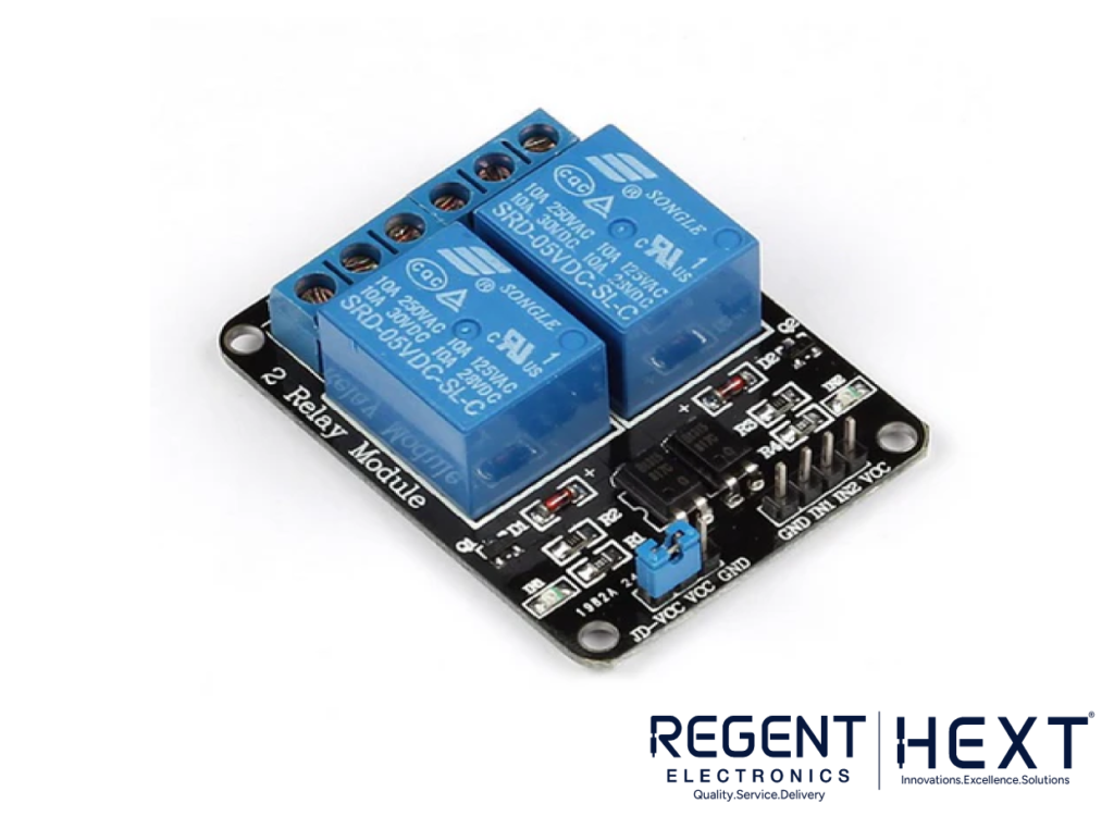

The Arduino can’t directly control high-voltage devices like lamps and fans, so we use a Relay Module to bridge this gap. A relay is an electrically operated switch, controlled by a low-power signal, that activates the high-power devices.
Relay Module Pinout:
- GND: Reference ground input.
- VCC: Provides 5V to power the relay circuit.
- JD-VCC: Isolated power supply input.
- IN1: Input to activate Relay 1.
- IN2: Input to activate Relay 2.
How Does It Work?
When you press a button on your TV/DVD/MP3 remote, the IR LED emits a signal at a unique frequency that is picked up by the TSOP1838 sensor. The Arduino decodes this signal, compares it to the predefined codes in the program, and turns the corresponding device (like a fan or bulb) on or off based on the remote input.
Wiring and Setup
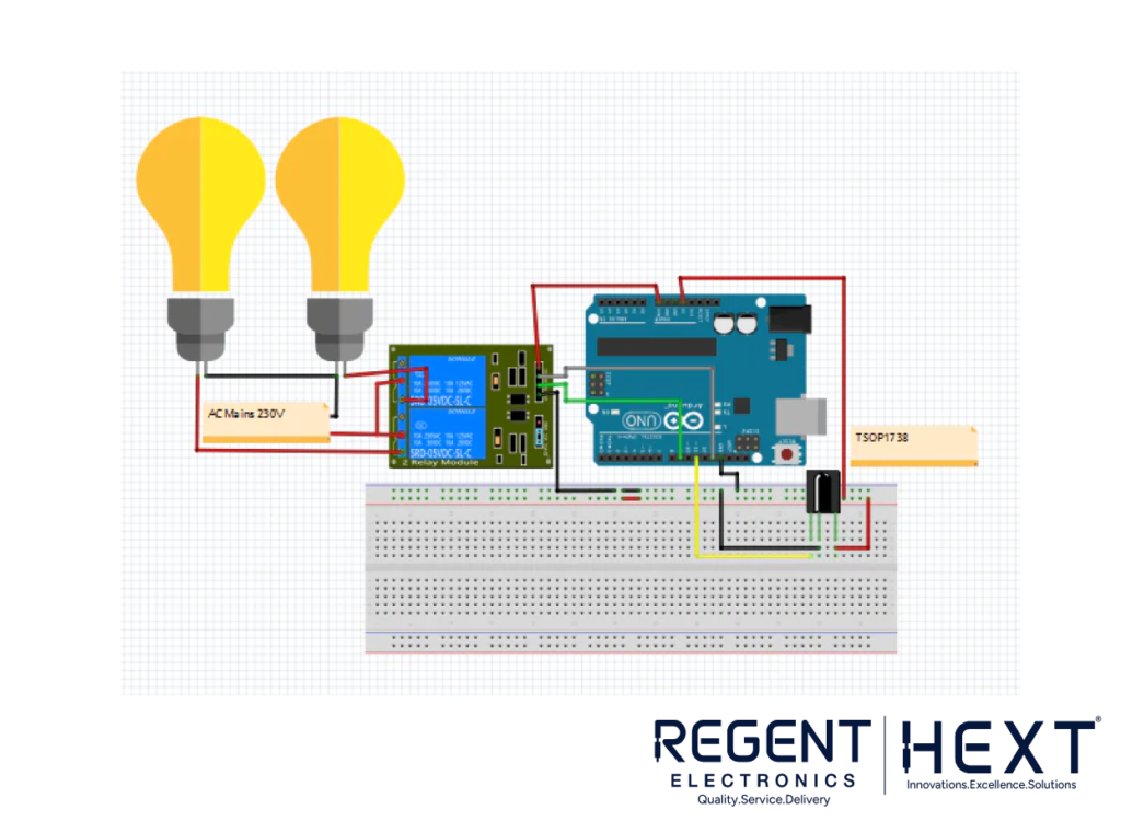
The setup is straightforward, involving connecting the TSOP1838 IR sensor to the Arduino and the Relay Module to control the high-voltage appliances. Here’s a simplified view of the circuit:
- Connect the TSOP1838 IR sensor to the Arduino using appropriate jumper wires.
- Connect the Relay Module to control appliances like the bulb or fan, ensuring that the relay is capable of handling AC voltage.
- Upload Code to Arduino and test the system with your remote control.
Install the IRremote Library
Before starting the project, install the IRremote library from the Arduino IDE. This library is essential to enable Arduino to communicate with the IR sensor. Once installed, you can upload a demo code to read the IR signal from your remote control.
Arduino Code Example:
cpp
CopyEdit
#include <IRremote.h>
int RECV_PIN = 11; // Pin connected to the IR receiver
int LED = 9; // Pin connected to the LED
int bulb = 13; // Pin connected to the Bulb
IRrecv irrecv(RECV_PIN);
decode_results results;
void setup() {
Serial.begin(9600);
pinMode(LED, OUTPUT);
pinMode(bulb, OUTPUT);
irrecv.enableIRIn(); // Start the IR receiver
}
void loop() {
if (irrecv.decode(&results)) {
Serial.println(results.value, HEX); // Print received code to Serial Monitor
if (results.value == 0x1801 || results.value == 0x1001) {
digitalWrite(LED, HIGH); // Turn on LED
} else if (results.value == 0x1802 || results.value == 0x1002) {
digitalWrite(LED, LOW); // Turn off LED
} else if (results.value == 0x1803 || results.value == 0x1003) {
digitalWrite(bulb, HIGH); // Turn on Bulb
} else if (results.value == 0x1804 || results.value == 0x1004) {
digitalWrite(bulb, LOW); // Turn off Bulb
}
irrecv.resume(); // Ready to receive the next IR signal
}
delay(100);
}
Conclusion
This DIY IR remote-controlled home automation system using Arduino is an innovative way to automate your home appliances without having to buy expensive smart devices. With just a few components and a simple Arduino program, you can control your lights, fans, and other devices from the comfort of your couch.
Whether you’re a beginner looking to dive into Arduino projects or a seasoned maker, this guide will provide you with the knowledge and tools needed to bring your home automation ideas to life. Happy building!
Stay Connected for More Arduino Projects & Tutorials from Regent Electronics!