
Rotary Encoder Arduino Code – A Detailed Guide
Introduction
A rotary encoder is a versatile device used for infinite rotation, making it ideal for applications requiring precise position tracking. Unlike potentiometers, rotary encoders do not have a defined start or end position. This tutorial will guide you through how rotary encoders work, their output, and how to run a rotary encoder Arduino code to read its output efficiently.
What is a Rotary Encoder?
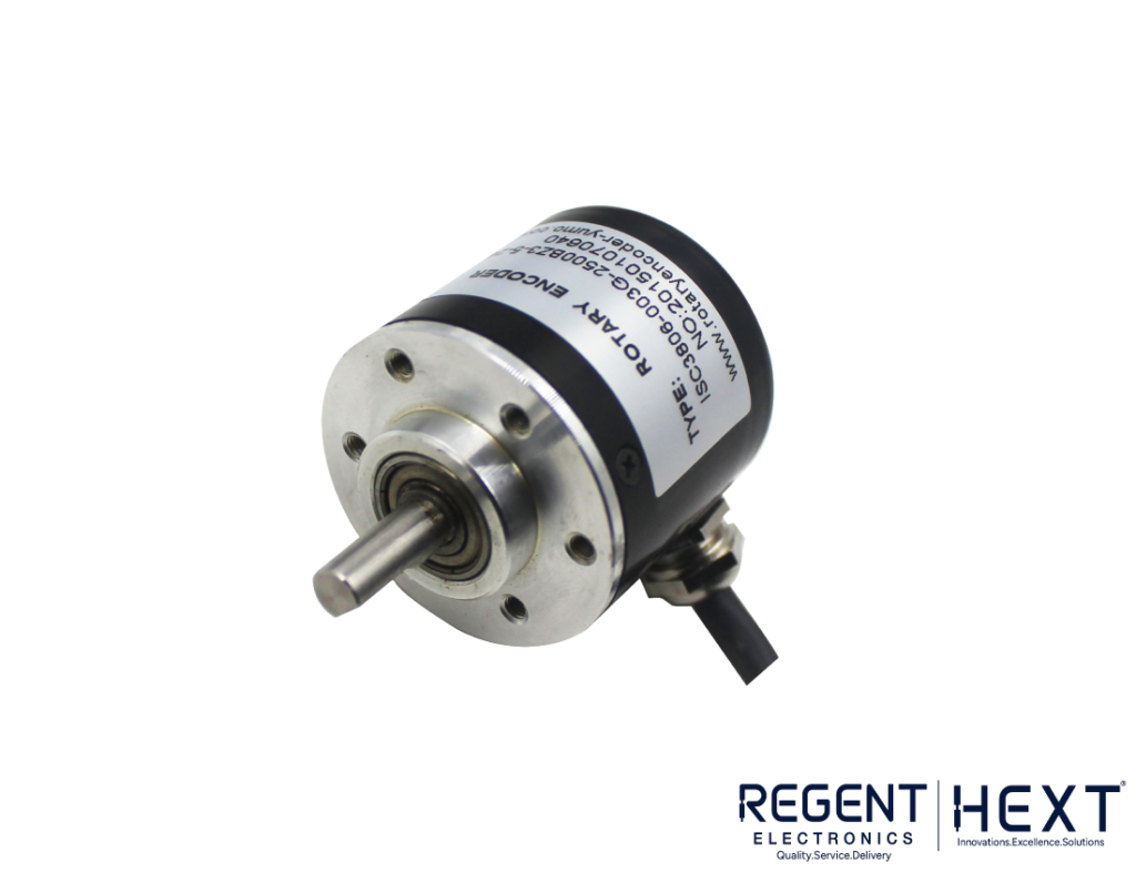
A rotary encoder is a position sensor that detects mechanical motion and converts it into an analog or digital signal. It helps measure position, while velocity, acceleration, and direction can be derived from the position in linear or rotary movement.
Since rotary encoders can rotate continuously without a predefined limit, their position must be tracked in code. This makes them perfect for use as knobs or control dials in various applications.
How Does a Rotary Encoder Work?
A basic rotary encoder consists of four main pins:
- VCC – Power supply
- GND – Ground
- CLK (Clock) – Provides a signal when rotated
- DT (Data) – Determines rotation direction
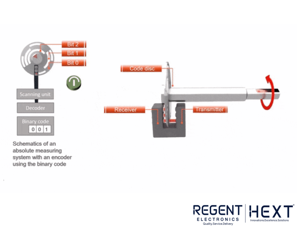
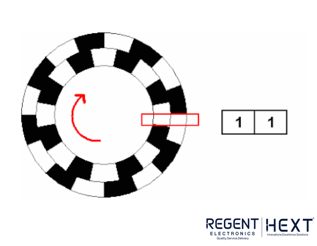
When the encoder rotates, the CLK and DT pins generate signals in a two-bit Gray code format: 00, 01, 10, and 11. The change in these values helps determine the direction of rotation.
Additionally, some rotary encoders include a SW (Switch) pin, which acts as a push-button when pressed.
Rotary Encoder Output
A rotary encoder generates a sequence of binary values that help detect motion. The change in state determines whether the rotation is clockwise or counterclockwise. This continuous tracking allows for precise control in applications like volume adjustment, menu navigation, and robotics.
Using Interrupts for Accurate Reading
For accurate tracking, the Arduino needs to register every state change of the encoder. However, if the Arduino is executing other tasks (e.g., delays), it might miss state changes. To avoid this, we use interrupts.
Interrupts allow the Arduino to immediately respond to a change in encoder state, ensuring no movement is missed. The Arduino has specific interrupt pins that can detect changes (rising, falling, or any change in state).
Understanding Rotary Encoder Code
To track the encoder movement, we treat the two signal pins (CLK and DT) as binary inputs, which can be 00, 01, 10, or 11. When the encoder moves, these values change in a predictable pattern. By comparing the previous and current values, we can determine the direction of rotation.
Code for Rotary Encoder with Arduino
// Define the pins for the rotary encoder
int encoderPin1 = 2; // Interrupt pin
int encoderPin2 = 3; // Interrupt pin
volatile int lastEncoded = 0;
volatile long encoderValue = 0;
long lastencoderValue = 0;
int lastMSB = 0;
int lastLSB = 0;
void setup() {
Serial.begin(9600);
pinMode(encoderPin1, INPUT);
pinMode(encoderPin2, INPUT);
digitalWrite(encoderPin1, HIGH); // Enable pull-up resistor
digitalWrite(encoderPin2, HIGH); // Enable pull-up resistor
// Attach interrupts to encoder pins
attachInterrupt(digitalPinToInterrupt(encoderPin1), updateEncoder, CHANGE);
attachInterrupt(digitalPinToInterrupt(encoderPin2), updateEncoder, CHANGE);
}
void loop() {
Serial.println(encoderValue);
delay(1000); // Delay for readability
}
void updateEncoder() {
int MSB = digitalRead(encoderPin1); // Most significant bit
int LSB = digitalRead(encoderPin2); // Least significant bit
int encoded = (MSB << 1) | LSB; // Convert to single value
int sum = (lastEncoded << 2) | encoded; // Combine with previous value
if (sum == 0b1101 || sum == 0b0100 || sum == 0b0010 || sum == 0b1011) encoderValue++;
if (sum == 0b1110 || sum == 0b0111 || sum == 0b0001 || sum == 0b1000) encoderValue–;
lastEncoded = encoded; // Store for next comparison
}
How the Code Works
- Pin Setup: The encoder pins are defined and initialized as input pins with pull-up resistors.
- Interrupts: The Arduino listens for changes in the encoder’s signal using interrupt service routines (ISR), ensuring real-time responsiveness.
- Tracking Movement: The Arduino determines direction by analyzing the sequence of binary values.
- Updating Position: Each detected movement updates the encoderValue, which can be used for applications like volume control or navigation.
Conclusion
Rotary encoders are powerful components for measuring motion and adjusting values in digital systems. By using interrupts, you can ensure accurate tracking of movements without missing steps. This guide covered the basics of rotary encoders, their working principles, and an efficient Arduino code to track rotary encoder movement.
For more electronics tutorials and sensor guides, stay tuned to Regent Electronics!