
Build an Arduino GPS Clock with Regent Electronics
Introduction
In this tutorial, we will guide you through the process of building an Arduino clock using the UBlox NEO-M8M GPS Module. While Arduino has an onboard timer, using an external GPS module simplifies the task and improves accuracy.
Why Use a GPS Module for an Arduino Clock?
An internal timer can be used to build a clock, but it may require additional programming and may not maintain accurate time over long periods. A GPS module provides precise time data directly from satellites, making it the best choice for an Arduino-based clock.
How a GPS Module Works for Timekeeping
Most GPS modules, including the UBlox NEO-M8M, provide location coordinates (latitude and longitude) along with real-time date and time information. The GPS module sends this data in serial format, and we use an Arduino to extract and display the time.
Understanding GPS NMEA Output
GPS modules output data in NMEA (National Marine Electronics Association) format. Among various data lines, we are particularly interested in the one starting with $GPRMC, which contains useful time-related information.
Example NMEA Output:

$GPRMC,182306,A,1523.82,N,00022.24,W,173.8,231.8,110120,004.2,W*70
- 182306 represents the Coordinated Universal Time (UTC) in hhmmss format.
- A indicates an active GPS signal, while V means no signal.
- The next values provide latitude and longitude.
- 110120 represents the date in DDMMYY format.
Required Components
Hardware Components:
- UBlox NEO-M8M GPS Module
- Arduino Board
- USB Cable
- Dupont Wires
- LCD Display
- Breadboard
- LiPo or Li-ion Battery
Software Requirements:
- Arduino IDE
Features of UBlox NEO-M8M GPS Module
- Supports multiple GNSS systems (GPS, Galileo, GLONASS, BeiDou)
- High sensitivity: –167 dBm
- Security and integrity protection
- Onboard ROM memory
- Advanced jamming and spoofing detection
Circuit Diagram
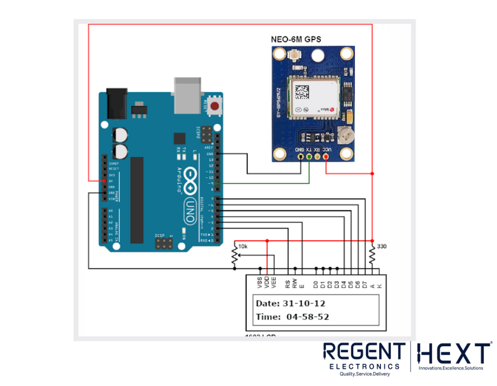
The following diagram illustrates the connection setup for the Arduino GPS Clock.
Connections:
- Connect the TX pin of the GPS module to pin D9 of the Arduino.
- Power the GPS module using the Arduino itself.
Arduino Code for GPS Clock
#include<LiquidCrystal.h>
LiquidCrystal lcd(7, 6, 5, 4, 3, 2);
#include <SoftwareSerial.h>
SoftwareSerial Serial1(9, 10); // RX, TX
char str[70];
char *test=”$GPRMC”;
int temp, i;
void setup()
{
lcd.begin(16,2);
Serial1.begin(9600);
lcd.setCursor(0,0);
lcd.print(“GPS Updated Clock”);
lcd.setCursor(0,1);
lcd.print(“Regent Electronics”);
delay(300);
}
void loop()
{
serial1Event();
if (temp)
{
lcd.clear();
int x = 0, comma = 0;
String UTC_hour = “”, UTC_minute = “”, UTC_second = “”;
String UTC_date = “”, UTC_month = “”, UTC_year = “”;
while (x < i)
{
if (str[x] == ‘,’)
comma++;
if (comma == 1) // Extract time
{
x++;
UTC_hour += str[x++]; UTC_hour += str[x++];
UTC_minute += str[x++]; UTC_minute += str[x++];
UTC_second += str[x++]; UTC_second += str[x];
comma = 2;
}
if (comma == 10) // Extract date
{
x++;
UTC_date += str[x++]; UTC_date += str[x++];
UTC_month += str[x++]; UTC_month += str[x++];
UTC_year += str[x++]; UTC_year += str[x];
}
x++;
}
int Hour = UTC_hour.toInt() + 5;
if (Hour > 23) { Hour -= 24; }
int Minute = UTC_minute.toInt() + 30;
if (Minute > 59) { Minute -= 60; }
lcd.clear();
lcd.print(“Date: “); lcd.print(UTC_date); lcd.print(“/”);
lcd.print(UTC_month); lcd.print(“/20”); lcd.print(UTC_year);
lcd.setCursor(0,1);
lcd.print(“Time: “); lcd.print(Hour); lcd.print(“:”);
lcd.print(Minute); lcd.print(“:”); lcd.print(UTC_second);
temp = 0; i = 0;
}
}
void serial1Event()
{
while (1)
{
while (Serial1.available())
{
char inChar = (char)Serial1.read();
str[i++] = inChar;
if (i < 7 && str[i-1] != test[i-1]) { i = 0; }
if (i > 65) { temp = 1; break; }
}
if (temp) break;
}
}
Conclusion
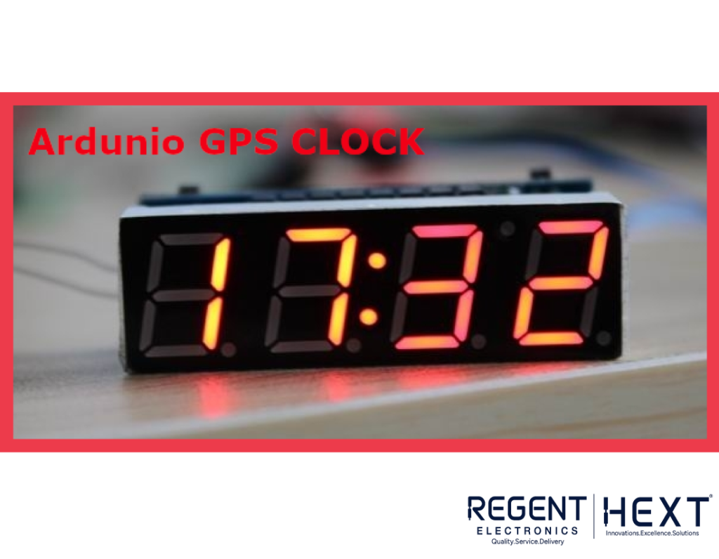
By following this guide, you have successfully built an Arduino GPS Clock using the UBlox NEO-M8M module. If you have any questions, feel free to ask in the comments. In our next tutorial, we will explore how to build an Arduino clock using the DS1307 RTC module. Stay tuned!
Regent Electronics – Your Partner in Innovation!