
Voice Controlled Wireless Notice Board: Revolutionizing Communication with Arduino

In today’s modern age, the need for efficient and wireless communication in public spaces, offices, hospitals, and canteens is crucial. Imagine being able to display important messages or notices instantly without the hassle of traditional paper methods. With the Voice Controlled Wireless Notice Board, powered by Arduino, 16×2 LCD, and the HC-05 Bluetooth module, you can seamlessly display messages on an LCD screen via Bluetooth communication from your smartphone. This innovative solution is far more efficient, secure, and convenient than conventional notice boards, offering real-time updates without the delay.
This technology has various applications, including:
- Hospitals: Display real-time alerts or patient notices.
- Offices: Show announcements, meeting schedules, or important office memos.
- Conference Rooms: Update meeting information or schedule changes instantly.
- Public Areas: Broadcast important community messages or public service announcements.
Components Required for the Project
To build the Voice Controlled Wireless Notice Board, you’ll need the following components:
- Arduino Board: The microcontroller for running the code and controlling the components.
- 16×2 LCD Display: To display the messages received via Bluetooth.
- HC-05 Bluetooth Module: Used to wirelessly communicate with the smartphone for message transmission.
- Connecting Wires: For wiring the components together.
- 1k, 2.2k, and 560-ohm Resistors: Essential for the circuit’s proper functioning.
- 10k Potentiometer: For adjusting the contrast of the LCD screen.
- USB Cable: To power the Arduino and upload the code.
- Power Supply: To power the entire system.

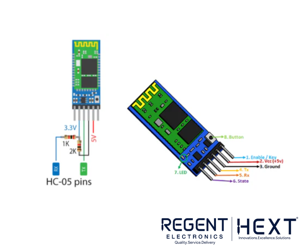
What is the HC-05 Bluetooth Module?
The HC-05 Bluetooth Module is an affordable and efficient Bluetooth solution, ideal for wireless communication between devices. It supports the Serial Port Protocol (SPP), which establishes a transparent wireless serial link between devices. The HC-05 module works in two modes:
- Data Mode: Used for transferring data wirelessly between devices.
- Command Mode: Used for setting configurations such as baud rate, password, and device name using AT commands.
Features of the HC-05 Bluetooth Module:
- Red LED Indicator: Shows the Bluetooth connection status. It blinks during pairing and turns solid when successfully connected.
- Voltage Compatibility: The HC-05 operates at 3.3V but is also compatible with 5V systems.
- Simple Configuration: With the AT commands, you can customize the module settings, such as changing the device name or baud rate.
How to Interface the 16×2 LCD with Arduino?
Connecting a 16×2 LCD to your Arduino is straightforward and requires basic knowledge of LCD pinout and interfacing. The JHD162A LCD is commonly used in Arduino projects and is based on the HD44780 driver. It has 16 pins, which can be configured in either 4-bit or 8-bit mode. For this project, we’ll use the 4-bit mode for simpler wiring.
Pinout for 16×2 LCD:
- Pin 1 (Vss): Ground pin.
- Pin 2 (Vcc): Power pin (+5V).
- Pin 3 (VEE): Contrast pin (connected to a 10K potentiometer).
- Pin 4 (RS): Register Select (used to switch between command and data modes).
- Pin 5 (R/W): Read/Write mode (set LOW for writing).
- Pin 6 (E): Enable pin (used to latch data).
- Pins 7-14 (DB0-DB7): Data pins.
- Pin 15 (Backlight +): Anode pin for the backlight LED.
- Pin 16 (Backlight -): Cathode pin for the backlight LED.
Circuit Diagram
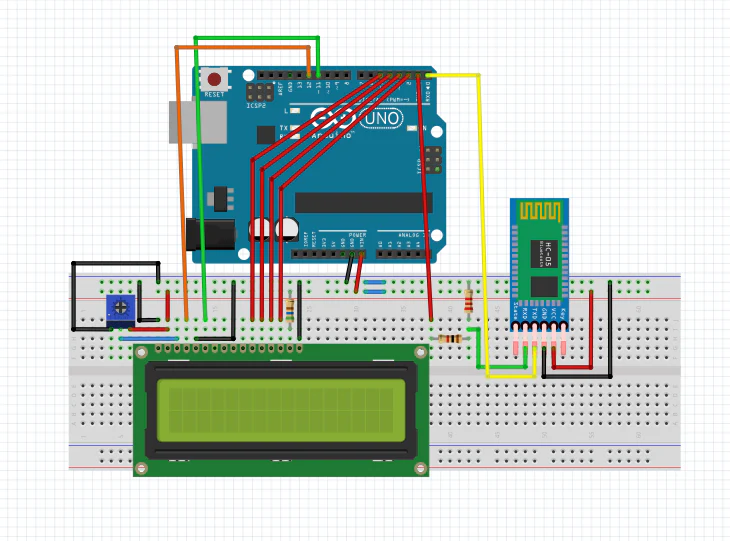
The circuit diagram for this project connects the Arduino to the HC-05 Bluetooth module and the 16×2 LCD display. Make sure to wire the components according to the pinout and schematic provided.
Arduino Code for Wireless Notice Board
Below is the Arduino code to implement the voice-controlled wireless notice board with Bluetooth communication:
cpp
CopyEdit
#include <LiquidCrystal.h>
// Initialize the LCD library with the correct pin numbers
LiquidCrystal lcd(12, 11, 5, 4, 3, 2); // RS, EN, D4, D5, D6, D7 pins
char str;
void setup() {
lcd.begin(16, 2); // Initialize the LCD with 16 columns and 2 rows
Serial.begin(9600); // Start serial communication at 9600 baud
}
int i = 0;
void loop() {
while(Serial.available()) {
str = Serial.read(); // Read the incoming data from Bluetooth
if(str == ‘*’) {
lcd.setCursor(0, i); // Set cursor to the current row
}
else if(str == ‘-‘) {
lcd.clear(); // Clear the display
delay(10);
}
else if(str == ‘#’) {
i = abs(i – 1); // Toggle between the two rows of the display
}
else if(str == ‘%’) {
while(str != ‘!’) {
str = Serial.read(); // Read data until ‘!’ is received
lcd.scrollDisplayLeft(); // Scroll the text to the left
delay(1000); // Wait for a second before scrolling again
}
}
else {
lcd.print(str); // Print the received character on the LCD
delay(200); // Delay for better display visibility
}
}
}
Conclusion
The Voice Controlled Wireless Notice Board is a simple yet powerful project that utilizes Arduino, Bluetooth, and an LCD display to create an efficient and wireless communication system. Whether in hospitals, offices, or public spaces, this system allows real-time message posting, eliminating the need for manual updates. By leveraging Bluetooth technology and Arduino, you can build a wireless notice board that streamlines communication in any environment.