
Everything You Need to Know About Relay Timer Modules
Relay Timer Modules are versatile components widely used in automation and time-delay applications. Whether you’re a beginner or an experienced electronics enthusiast, understanding how to work with these modules is essential. This guide provides a comprehensive overview of the Relay Timer Module, including its features, pinout, connection setup, operational modes, and specifications.
What is a Relay Timer Module?
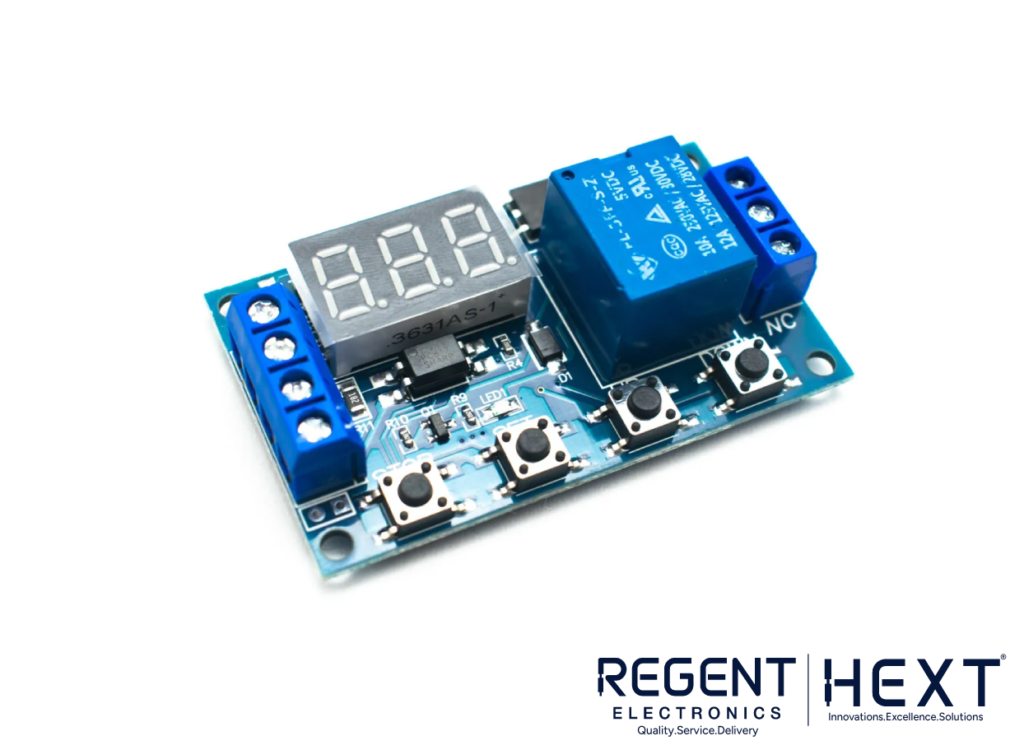
A Relay Timer Module is a compact device designed for time-delay control in automation systems. Equipped with an adjustable timing cycle, switches, and a digital LED display, it’s an ideal choice for tasks like home automation, delay switches, and more. The module supports an operating voltage range of 6–30V via terminal blocks and can also be powered with 5V using a micro USB connection.
The module’s relay is capable of handling loads up to 30V DC at 10A or 250V AC at 10A. It allows users to control when the relay is in the normally open (NO) or normally closed (NC) state for a specified duration.
Key Features
- Adjustable Timing Cycle: Allows precise control of time delays.
- Multiple Powering Options: Operates via terminal blocks, micro USB, or soldered wires.
- Digital Display: Simplifies mode selection and time adjustment.
- Wide Voltage Range: Supports 6–30V input with anti-interference capabilities.
- High Load Capacity: Handles up to 30V DC / 250V AC at 10A.
Pinout and Connections
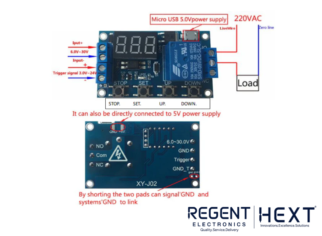
Powering the Module
- Terminal Blocks: Accepts a voltage range of 6–30V DC.
- Micro USB Port: Can be powered using a 5V USB connection.
- Soldered Wires: An alternative method to connect a 5V power supply by soldering wires directly to designated points on the module.
Triggering Signal
The third and fourth terminal blocks are designated for triggering the module. They support a high-level trigger signal between 3–24V. The signal can come from a microcontroller, push button, or switch. The module’s common ground setup enhances its anti-interference capabilities.
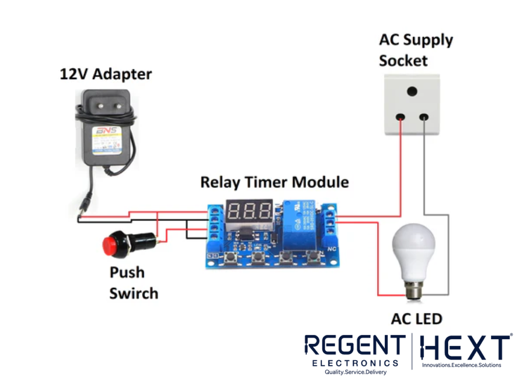
Relay Output
The module features three output terminals:
- NO (Normally Open): Connected when the relay is activated.
- COM (Common): The central connection point.
- NC (Normally Closed): Disconnected when the relay is activated.
The relay can switch loads of up to 30V DC or 250V AC at 10A, making it suitable for driving LEDs, motors, or other devices.
Understanding the Onboard Switches
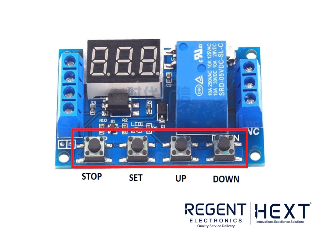
- SET Button: Used for selecting operational modes. Long-pressing it displays the available modes on the digital display.
- UP/DOWN Buttons: Used for navigating between modes or adjusting timing values.
- STOP Button: Allows the module to be turned on or off. Long-pressing it toggles between sleep mode (C-P) and normal display mode (O-d).
Operation Modes Explained
The Relay Timer Module supports several operational modes (P1 to P4), each with specific functions:
P1 Modes:
- P1.1: The relay remains ON (NO) for a set time and OFF (NC) afterward.
- P1.2: Similar to P1.1, but triggering during the ON period restarts the timer.
- P1.3: Triggering during the ON period pauses the timer until triggered again.
- P1.4: Starts automatically when powered without requiring a trigger signal.
P2 Modes:
- P2.1: Allows setting both ON and OFF times. Triggering during the ON period has no effect.
- P2.2: Similar to P2.1 but restarts the timer when triggered again.
- P2.3: Triggering pauses the timer until activated again.
P3 Modes:
- P3.1: Combines ON, OFF, and repeat cycles (LOP). Pauses when triggered during a cycle.
- P3.2: Functions like P3.1 but starts automatically when powered.
P4 Mode:
This mode introduces a signal-holding function. The relay remains ON as long as the trigger signal is active.
LED Indicators
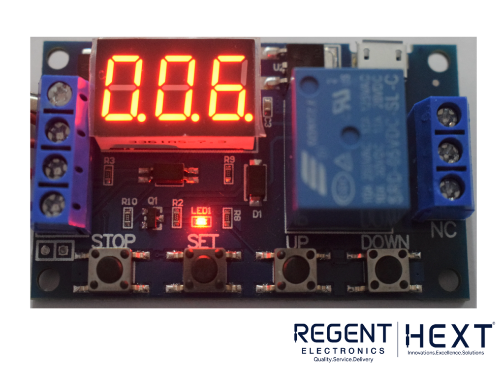
- The digital display provides clear feedback on timing values and modes.
- An onboard red LED indicates when the relay is in the ON state (NO).
Specifications
| Parameter | Value |
| Operating Voltage | 6–30V DC |
| Trigger Voltage | 3–24V DC |
| Output Voltage (AC) | Up to 250V at 10A |
| Output Voltage (DC) | Up to 30V at 10A |
| Current Consumption | 50mA |
| Operating Temperature | -40°C to +85°C |
Practical Usage Guide
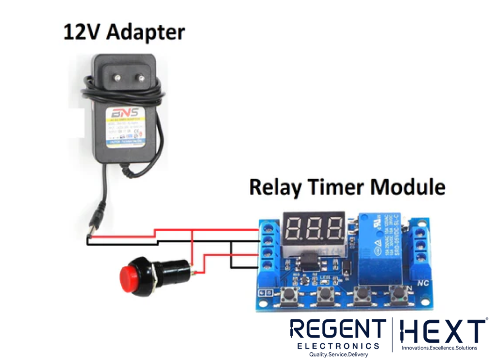
- Connecting the Power Supply: Use a 12V adapter or any DC source within the operating range.
- Triggering the Relay: Attach a push button or microcontroller to the trigger pins.
- Driving a Load: Connect the load (e.g., an LED or motor) to the relay’s NO, COM, and NC terminals. Ensure the load current does not exceed 10A.
Applications
- Home Automation: Timed switching of appliances.
- Industrial Control: Precise control of motors and actuators.
- DIY Projects: Experimentation and prototyping.
- Lighting Systems: Timed ON/OFF control for LEDs or lamps.
The Relay Timer Module is a powerful and flexible solution for any project requiring time-based control. With its user-friendly design and robust functionality, it’s a must-have for both beginners and professionals.
Shop now at Regent Electronics for high-quality Relay Timer Modules and elevate your next project!