
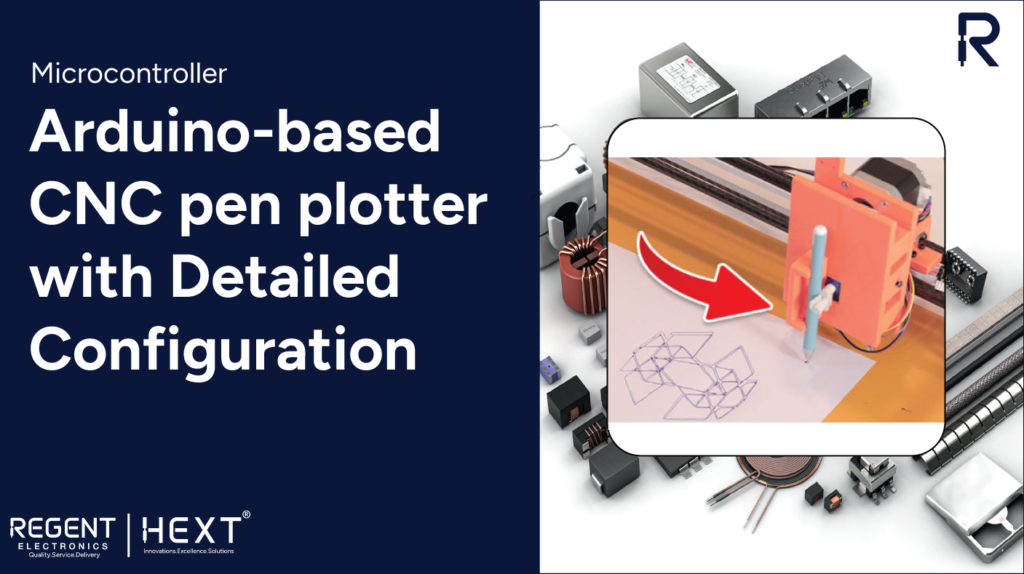
How to Build an Arduino-based CNC Pen Plotter: A Complete Guide
Are you looking to create an impressive CNC pen plotter? This guide will walk you through the steps to build your very own CNC pen plotter using Arduino. Whether you’re an electronics enthusiast or a DIYer, this project will be an excellent addition to your workspace, allowing you to create intricate designs and drawings with ease. Let’s dive into the details!
What is a CNC Pen Plotter?
A CNC (Computer Numerical Control) pen plotter is a machine that uses a pen and a series of movements to draw images, text, or patterns on a flat surface. With a CNC plotter, you can control the motion of the pen in both the X and Y axes to create precise drawings based on the instructions you provide through G-code programming. By using Arduino as the main controller, this project allows you to build your own CNC plotter easily.
Components Required for the Project
To build an Arduino-based CNC pen plotter, you’ll need the following components:
- Arduino UNO
- CNC Shield
- A4988 Stepper Motor Driver
- NEMA17 Stepper Motors
- Servo Motor
- 12mm and 6mm Carbon Tubes
- 6mm Rods
- Timing Belt
- Linear Bearings (6mm and 12mm)
- NEMA17 Stepper Mounting Brackets
- 3D Printed End Plates (for the structure)
- Various nuts, bolts, and screws
- Pen Holder Mechanism

You can print the structure if you don’t have access to a 3D printer by using a local 3D printing service.
Assembling the CNC Pen Plotter

Step 1: Prepare the Structure
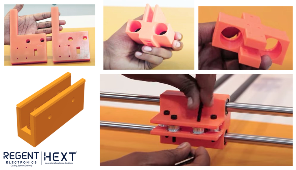
Start by preparing the end plates and gantry assembly. The end plates act as the base of your plotter. Attach the linear bearings into the gantry, ensuring they are correctly aligned.
Step 2: Insert the Carbon Tubes
Now, insert two 12mm carbon tubes into the center of the gantry. These will serve as the primary rods that allow the gantry to slide smoothly along its path.
Step 3: Attach the Slider Mechanism
Next, place the slider on the carbon tubes. Fix it in place using bearings and secure the arm end at the end of the carbon tube using bolts.
Step 4: Mount the Stepper Motors
Now, mount NEMA17 stepper motors on the stepper motor mounting brackets at each end plate. Attach pulleys to each motor shaft and secure them with bolts.
Step 5: Install the Timing Belt
Connect the timing belts between the pulleys as shown in the design. This will enable precise movements of the gantry.
Step 6: Assemble the Pen Holding Mechanism
Now, create the pen holder mechanism, which consists of a sliding part and a fixed part. Attach a servo motor to the sliding part. This servo will control the lifting and lowering of the pen during the drawing process. Insert linear bearings to allow smooth movement.
Step 7: Final Assembly
Attach the pen holder mechanism to the gantry, ensuring it can move in sync with the plotter’s motion. At this point, the mechanical assembly of your CNC pen plotter is complete.
Wiring the Electronics
The next step is to wire the electronics. We’ll use an Arduino UNO and a CNC shield to control the stepper motors. The CNC shield is a versatile driver expansion board that can be used for CNC machines, 3D printers, and engraving machines.
- The A4988 stepper motor drivers will control the movement of the stepper motors based on the instructions from the Arduino.
- Connect the servo motor to control the pen’s lifting mechanism.
- Connect the stepper motors to the CNC shield’s stepper driver slots.
Once your wiring is complete, you’re ready to install the necessary software and configure your CNC pen plotter.
Installing GRBL Firmware
To turn your Arduino into a true CNC machine, you’ll need to install the GRBL firmware. GRBL is an open-source firmware that allows you to control your CNC machine using G-code.
Step 1: Download GRBL
You can download the GRBL Pen Servo firmware from GitHub: GRBL Pen Servo. Once downloaded, extract the files and copy the grbl folder to the Arduino libraries folder.
Step 2: Modify the GRBL Code
You will need to modify the config.h file to activate Core XY mode. Use a text editor like Notepad++ to make the necessary changes.
Step 3: Upload GRBL to Arduino
Open the Arduino IDE, select grblUpload.ino, compile the code, and upload it to your Arduino.
Configuring GRBL
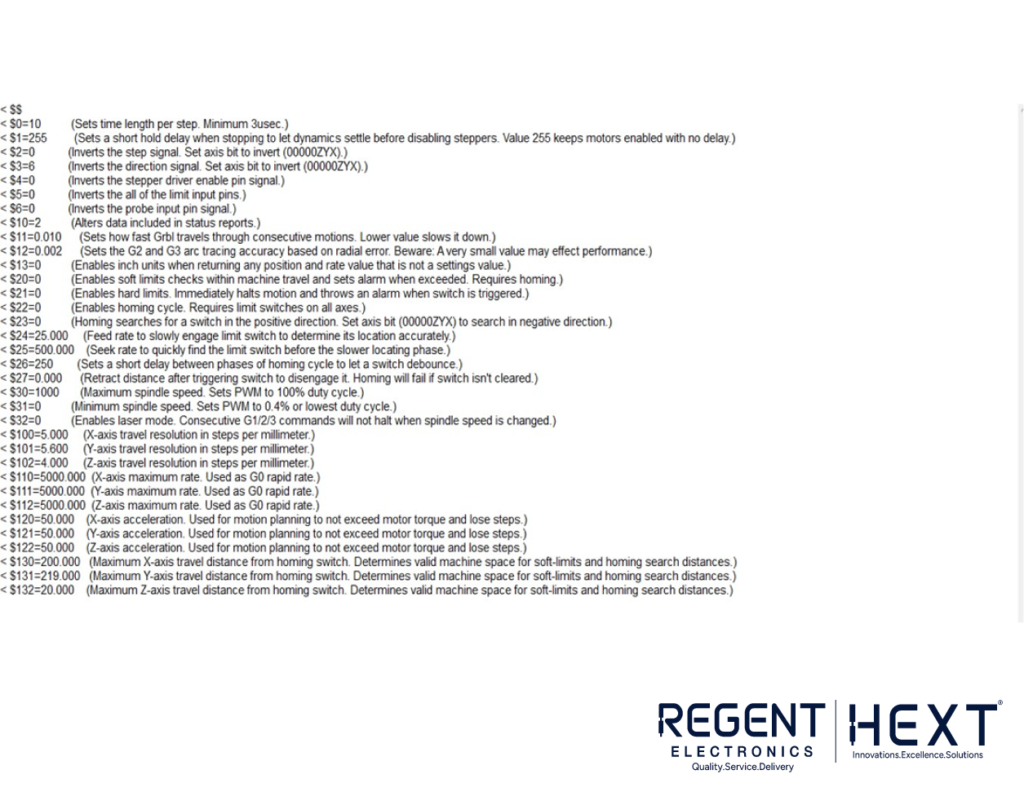
Once GRBL is uploaded, connect your Arduino to the Serial Monitor at 115200 baud to configure your settings. Enter $$ in the Serial Monitor to view your current GRBL settings.
You can adjust the settings by entering commands like:
$110=6000
This command will set the maximum speed for the X-axis. You can adjust other parameters as needed for optimal performance.
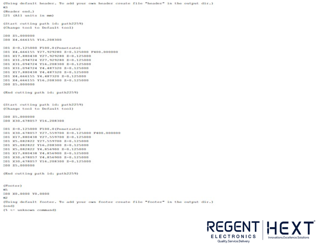
Plotting an Image
To plot an image, you will need to generate a G-code file. You can use Inkscape (a free vector graphics editor) to create or convert your image into G-code format.
Step 1: Install UGS (Universal Gcode Sender)
Download and install UGS Classic: Download UGS. UGS allows you to send G-code to your CNC plotter.
Step 2: Connect to Your CNC Pen Plotter
Once UGS is installed, open it and connect to your Arduino. Set the communication speed to 115200 baud and select the correct COM port.
Step 3: Send G-code to Plotter
Browse for your G-code file and click Open. Then click Send to start the plotting process.
Conclusion
Congratulations! You’ve now built an Arduino-based CNC pen plotter capable of drawing intricate designs and images. With the ability to control the plotter through G-code and Arduino, you can unleash your creativity and bring your digital designs to life.
For more exciting DIY electronics projects, be sure to explore other tutorials. Happy plotting!
This version of the blog removes any references to specific companies while retaining all of the essential information.