
Traffic Light Controller Using Arduino – A Simple Solution for Traffic Management
Introduction to Traffic Light Controller Project
At Regent Electronics, we bring you an exciting and educational project idea to understand how traffic light systems work. This simple traffic light controller uses the popular Arduino microcontroller to simulate the functioning of a three-way traffic light system. With a few basic components and easy-to-follow steps, you can create a functional traffic light controller for educational or DIY projects. This system provides an opportunity to explore how traffic light sequencing helps manage traffic flow and reduce congestion.
The Importance of Traffic Light Systems
Traffic light systems are essential in managing the flow of vehicles and pedestrians at intersections. Without proper guidance and supervision, roads can become chaotic, leading to accidents and delays. Traffic signals help ensure safe road usage by instructing drivers on when to stop, slow down, or proceed.
Each light on the traffic signal represents a command for drivers:
- Red light: Stop
- Yellow light: Slow down and prepare to stop
- Green light: Go
By using this basic system, traffic light controllers help maintain order, reduce accidents, and ensure smooth vehicle movement.
Components Required for the Traffic Light Controller
To build the traffic light controller using Arduino, you will need the following components:
- Arduino Uno board
- Breadboard
- LEDs (Red, Yellow, Green)
- Resistors (220 Ohms)
- Dupont Cables
Circuit Setup for Traffic Light System
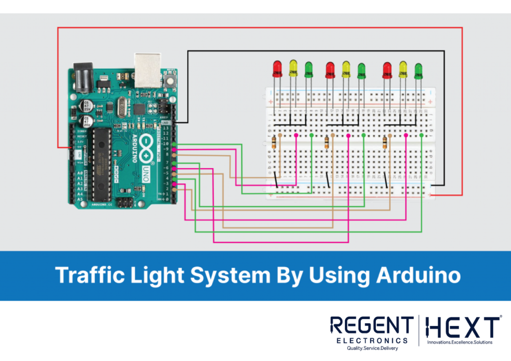
The setup is straightforward and can be easily built on a breadboard. Here’s how you can connect the components:
- Place the LEDs (Red, Yellow, and Green) on the breadboard.
- Connect the negative terminal of each LED and attach a 220-ohm resistor in series.
- Link the negative terminals to ground (GND).
- Connect the positive terminals of the LEDs to Arduino pins (2 to 10, respectively).
- Power the breadboard using 5V and GND from the Arduino.
Arduino Code for Traffic Light Controller
The code for this traffic light system controls the sequence of the LEDs to simulate the traffic light changes. Here’s a simple explanation of how it works:
- Initially, one set of red LEDs will turn on, signaling to the vehicles that they need to stop.
- After a few seconds, the yellow LEDs will briefly turn on, indicating that the light is about to change.
- Finally, the green LEDs will turn on, allowing traffic to flow.
The sequence will repeat continuously, with the LEDs following a fixed pattern of red, yellow, and green lights.
Arduino Code:
cpp
CopyEdit
void setup() {
// Configure output pins
pinMode(2, OUTPUT); // Red light 1
pinMode(3, OUTPUT); // Yellow light 1
pinMode(4, OUTPUT); // Green light 1
pinMode(5, OUTPUT); // Red light 2
pinMode(6, OUTPUT); // Yellow light 2
pinMode(7, OUTPUT); // Green light 2
pinMode(8, OUTPUT); // Red light 3
pinMode(9, OUTPUT); // Yellow light 3
pinMode(10, OUTPUT); // Green light 3
}
void loop() {
// First set of lights (Red, Yellow, Green for 1st lane)
digitalWrite(2, HIGH); // Red
digitalWrite(3, LOW); // Yellow
digitalWrite(4, LOW); // Green
delay(5000); // Wait for 5 seconds
digitalWrite(3, HIGH); // Yellow light ON for 1 second
delay(1000);
// Second set of lights (Green, Yellow, Red for 2nd lane)
digitalWrite(5, HIGH); // Red
digitalWrite(6, LOW); // Yellow
digitalWrite(7, HIGH); // Green
delay(5000); // Wait for 5 seconds
digitalWrite(6, HIGH); // Yellow light ON for 1 second
delay(1000);
// Third set of lights (Red, Yellow, Green for 3rd lane)
digitalWrite(8, HIGH); // Red
digitalWrite(9, LOW); // Yellow
digitalWrite(10, HIGH); // Green
delay(5000); // Wait for 5 seconds
digitalWrite(9, HIGH); // Yellow light ON for 1 second
delay(1000);
}
Output and Functionality
Once the code is uploaded to your Arduino Uno, the system will simulate the working of a traffic light controller by switching between red, yellow, and green LEDs. This mimics the operation of an actual traffic signal at an intersection, where vehicles must stop at the red light, slow down for the yellow light, and proceed when the green light is on.
Watch the output in action – the system will cycle through the lights in sequence:
- Red for 5 seconds
- Yellow for 1 second
- Green for 5 seconds
Advantages of the Traffic Light Controller System
- Practical Application: This system is a great learning tool for understanding how traffic light controllers work.
- Expandable: You can easily expand this project by adding additional functionality, such as crosswalk signaling, or adjusting the timings dynamically using external memory.
- Cost-Effective: With minimal components required, this project offers a budget-friendly way to build a traffic light control system.
Limitations of the System
- Not for Real-World Use: While this project offers a basic understanding of how traffic light systems work, it’s not suitable for real-world deployment.
- Manual Operation: The system is pre-programmed, and cannot handle real-time adjustments like a fully automated traffic management system.
- Static Timings: The timing for each light is fixed and cannot be changed during operation, unlike real systems where traffic timings may vary depending on traffic flow.
Final Thoughts

Thank you for exploring the Traffic Light Controller using Arduino with us at Regent Electronics. This project is a great way to get hands-on experience with basic electronics, microcontroller programming, and traffic management systems. If you enjoyed this project, we encourage you to try it out yourself, and feel free to share your experiences and improvements in the comments section below!