
How to Build a Line Follower Robot Car: A Step-by-Step Guide from Regent Electronics
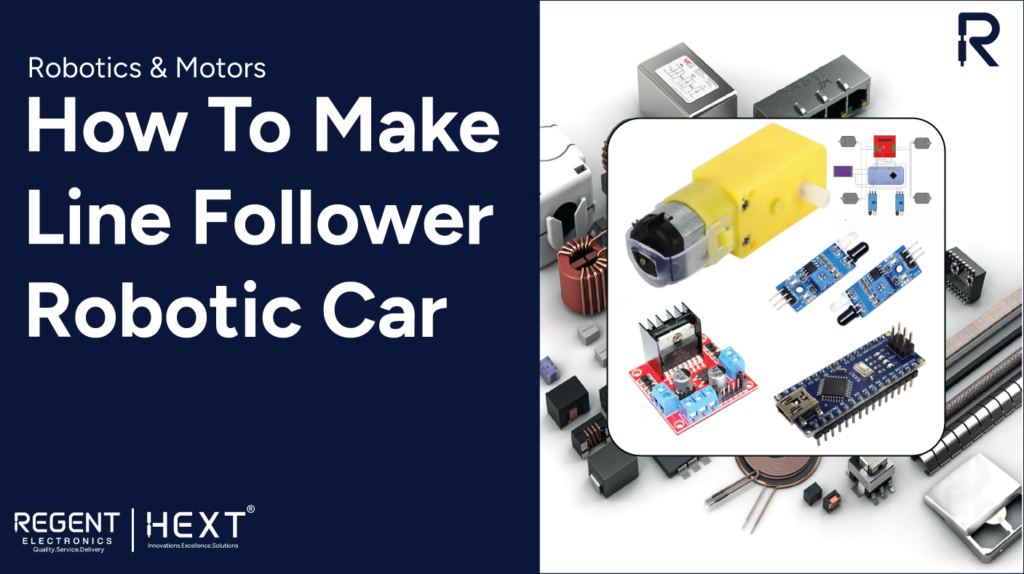
In today’s world, automation systems are revolutionizing the way industries operate, offering enhanced efficiency and reducing human intervention. One such exciting example of automation is the line follower robot car—a robot that can autonomously follow a black line path, much like a self-driving car navigating a roadway.
At Regent Electronics, we’re excited to walk you through the process of building your very own line follower robot car. This DIY project utilizes a few basic components like Arduino, IR sensors, and motor drivers to create a simple, yet fascinating robotic system. Let’s dive into the materials you’ll need and how to set up your line follower robot!
Components Needed for Building a Line Follower Robot Car
Before you start, ensure you have the following components. All items are easily available for purchase, and we have included links for your convenience.
Hardware Requirements
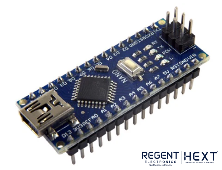
- Arduino Nano: The brain of your robot, this microcontroller will execute the robot’s commands. It has input/output pins that are easily programmable using the Arduino IDE.
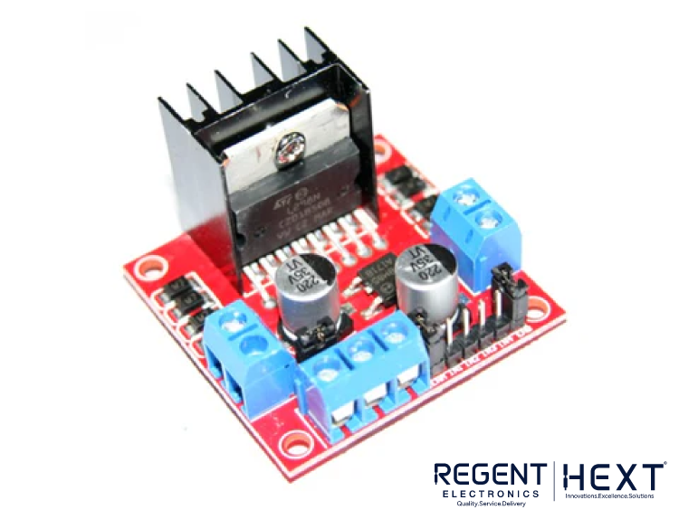
Buy Arduino Nano here - L298N Motor Driver: This motor driver controls the motors by providing the required current and voltage. It also allows you to control the speed via PWM (Pulse Width Modulation).
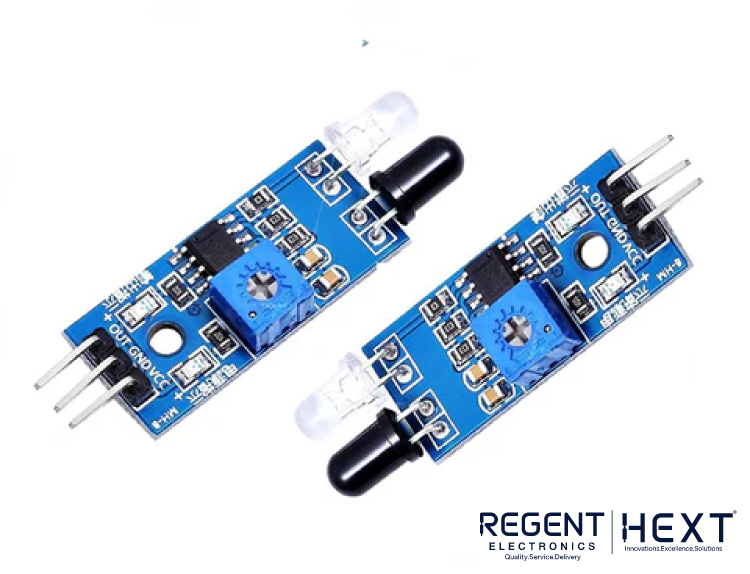
Buy L298N Motor Driver here - IR Sensors (2): Infrared (IR) sensors are essential for detecting the black line on the surface. They use infrared light to sense the contrast between the black line and the white background.
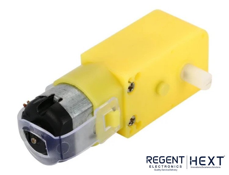
Buy IR Sensors here - DC Gear Motors (4): These motors provide good torque and speed for moving the robot along the path.
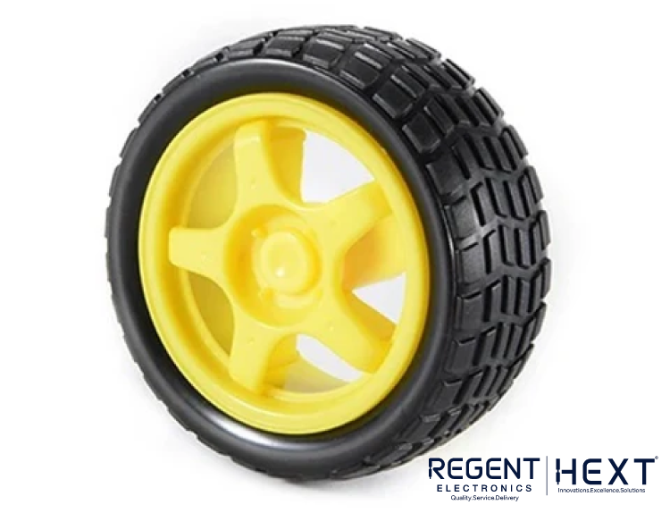
Buy DC Gear Motors here - Wheels (4): 65mm diameter wheels that easily attach to the DC gear motors.
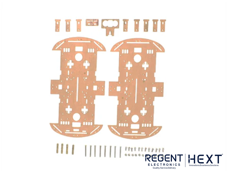
Buy Wheels here - Chassis with Fittings: The frame that holds all the components together. We recommend using an acrylic chassis for easy setup and durability.
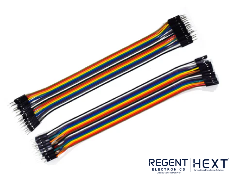
Buy Chassis here - Jumper Wires: These are used for making all necessary connections between the components.
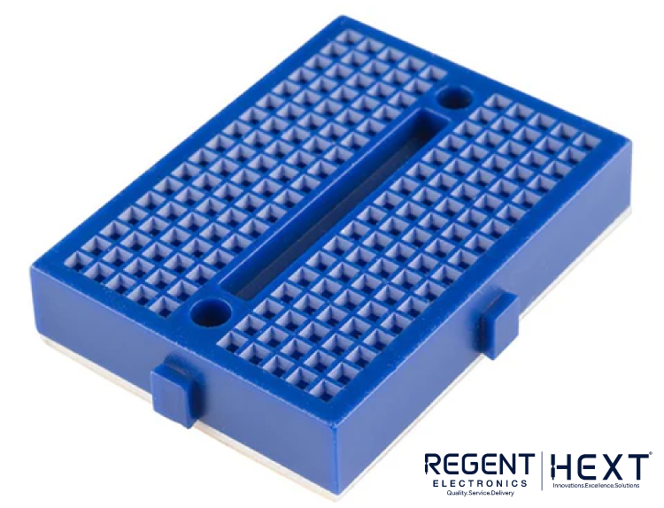
Buy Jumper Wires here - Breadboard: A breadboard is used for temporary circuit connections, especially during prototyping.
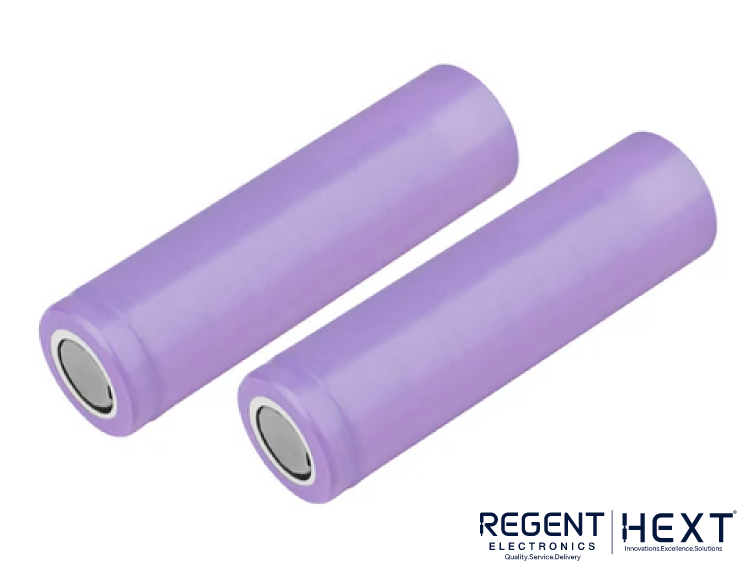
Buy Breadboard here - Li-ion Cells (2): Two rechargeable 18650 Li-ion cells to power the motors and Arduino board.
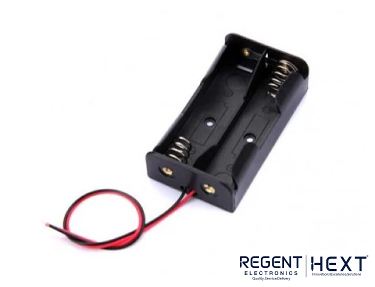
Buy Li-ion Cells here - Battery Holder: A two-cell battery holder to provide the required power.
Buy Battery Holder here
Software Requirements
- Arduino IDE: The open-source software where you’ll write the code that controls the robot. It allows you to upload the program to the Arduino board using a USB cable.
Download Arduino IDE here
Circuit Connection and Setup
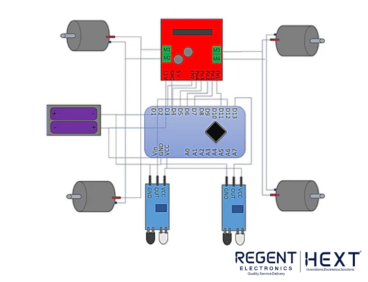
Pin Connections:
- Arduino Nano: Fix the Arduino Nano onto the breadboard.
- L298N Motor Driver:
- Connect EN1 and EN2 to D3 and D11 on the Arduino.
- Connect IN1, IN2, IN3, and IN4 to D4, D5, D6, and D7 on the Arduino.
- Connect the left motors to OUT1 and OUT2, and the right motors to OUT3 and OUT4.
- IR Sensors: Connect the OUT, VCC, and GND pins of the left IR sensor to D12, VCC, and GND of the Arduino, respectively. Similarly, connect the right IR sensor to D13, VCC, and GND.
- Power Connections:
- Connect the Vin and GND pins of the Arduino to the positive and negative terminals of the battery holder.
- Connect the VS (12V) and GND pins of the L298N to the battery holder.
Understanding the Working of the Line Follower Robot
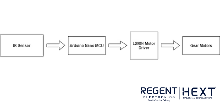
The primary function of this robot is to follow a black line on a white surface. This is achieved through IR sensors that detect the contrast between the black line and the white surface. Here’s how it works:
- IR Sensor Function: The IR sensors emit infrared rays that reflect off objects. When the sensor is over the black line, the infrared rays are absorbed and not reflected back, signaling the sensor that the robot is on the line.
- Robot Movement: The robot’s movement is controlled by the signals from the IR sensors:
- Move Forward: When both IR sensors detect the black line, they output a LOW signal, causing the robot to move forward.
- Turn Left: If the left IR sensor does not detect the black line, it outputs a HIGH signal, and the robot turns left.
- Turn Right: Similarly, if the right IR sensor does not detect the black line, it outputs a HIGH signal, and the robot turns right.
Flowchart for Line Follower Robot Control
The flowchart below explains the decision-making process for controlling the robot’s movement based on the input from the IR sensors. It helps in understanding how the robot determines whether to move forward, turn left, or turn right.
Programming the Line Follower Robot
Once the circuit is set up, it’s time to write the code. Below is the code that helps your robot make decisions based on the IR sensor readings:
cpp
CopyEdit
// Define pins for motors and sensors
#define motorLeft1 4
#define motorLeft2 5
#define motorRight1 6
#define motorRight2 7
#define sensorLeft A0
#define sensorRight A1
void setup() {
// Set motor pins as outputs
pinMode(motorLeft1, OUTPUT);
pinMode(motorLeft2, OUTPUT);
pinMode(motorRight1, OUTPUT);
pinMode(motorRight2, OUTPUT);
// Set sensor pins as inputs
pinMode(sensorLeft, INPUT);
pinMode(sensorRight, INPUT);
}
void loop() {
int leftSensor = digitalRead(sensorLeft);
int rightSensor = digitalRead(sensorRight);
if (leftSensor == LOW && rightSensor == LOW) {
// Move forward
digitalWrite(motorLeft1, HIGH);
digitalWrite(motorLeft2, LOW);
digitalWrite(motorRight1, HIGH);
digitalWrite(motorRight2, LOW);
}
else if (leftSensor == HIGH && rightSensor == LOW) {
// Turn left
digitalWrite(motorLeft1, LOW);
digitalWrite(motorLeft2, LOW);
digitalWrite(motorRight1, HIGH);
digitalWrite(motorRight2, LOW);
}
else if (leftSensor == LOW && rightSensor == HIGH) {
// Turn right
digitalWrite(motorLeft1, HIGH);
digitalWrite(motorLeft2, LOW);
digitalWrite(motorRight1, LOW);
digitalWrite(motorRight2, LOW);
}
}
This code reads the values from the IR sensors and controls the motors based on the sensor inputs.
Conclusion
Building a line follower robot car is an exciting and rewarding project. It introduces you to the basics of Arduino programming, IR sensors, and motor control. By following the step-by-step guide above, you can create your own automated robot that can follow a black line autonomously.
At Regent Electronics, we’re committed to making learning fun and engaging through practical projects. So, grab your line follower robot kit, and start building today!