

Top 5 DIY Projects Using Regent Electronics 37-in-1 Arduino Sensor Kit – With Circuit Diagrams
Are you ready to dive into the world of electronics and Arduino? The Regent Electronics 37-in-1 Sensor Kit is the perfect tool to get started. In this blog, we’ll guide you through 5 beginner-friendly electronics projects that use sensors from this kit. These projects include detailed working concepts and circuit diagrams to help you build with confidence.
Project 1: 🔥 Fire Alarm System Using Flame Sensor

📦 Components Required:
- Flame Sensor
- Arduino Uno
- Buzzer
- 220Ω resistor
- Jumper wires
- Breadboard
🔧 Working:
The flame sensor detects infrared light emitted by fire. When it senses flames, it sends a LOW signal to Arduino, which triggers a buzzer alarm.
🔌 Circuit Connections:
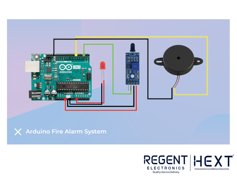
- Flame Sensor OUT → Arduino pin D2
- Buzzer +ve → Arduino pin D9
- Buzzer -ve → GND
- Sensor VCC → 5V, GND → GND
scss
CopyEdit
[ Flame Sensor ] –(OUT)–> [ D2 Arduino ]
[ Buzzer ] –(Positive)–> [ D9 Arduino ]
🧠 Code Logic (Simplified):
cpp
CopyEdit
if (digitalRead(2) == LOW) {
digitalWrite(9, HIGH); // Fire detected
} else {
digitalWrite(9, LOW); // No fire
}
✅ Application:
Useful as a prototype for home fire safety systems or kitchen smoke detection.
Project 2: 👏 Clap Switch Using Sound Sensor

📦 Components Required:
- Sound Sensor
- Arduino Uno
- Relay Module or LED
- Jumper wires
🔧 Working:
The sound sensor detects sudden audio spikes (like a clap) and sends a HIGH signal to Arduino. The controller toggles an LED or relay on each valid sound pulse.
🔌 Circuit Connections:
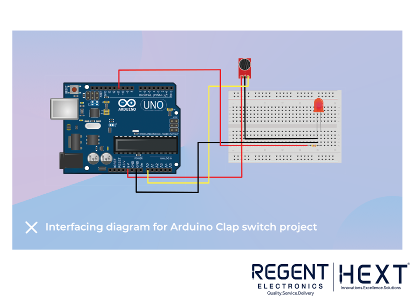
- Sound Sensor OUT → Arduino D2
- Relay IN → Arduino D8
- Sensor VCC → 5V, GND → GND
scss
CopyEdit
[ Sound Sensor ] –(OUT)–> [ D2 Arduino ]
[ Relay Module ] –(IN)–> [ D8 Arduino ]
🧠 Code Logic:
cpp
CopyEdit
if (digitalRead(2) == HIGH) {
digitalWrite(8, !digitalRead(8)); // Toggle state
delay(300); // Debounce
}
✅ Application:
Makes a hands-free switch—ideal for bedrooms, lights, or small fans.
Project 3: 🚪 Door Monitoring System Using Reed Switch

📦 Components Required:
- Magnetic Reed Switch
- Arduino Uno
- LED or Buzzer
- 10kΩ pull-down resistor
- Jumper wires
🔧 Working:
The reed switch closes its circuit when the magnet is nearby (door shut). Arduino reads this state and triggers an output when the door opens (magnet separates).
🔌 Circuit Connections:
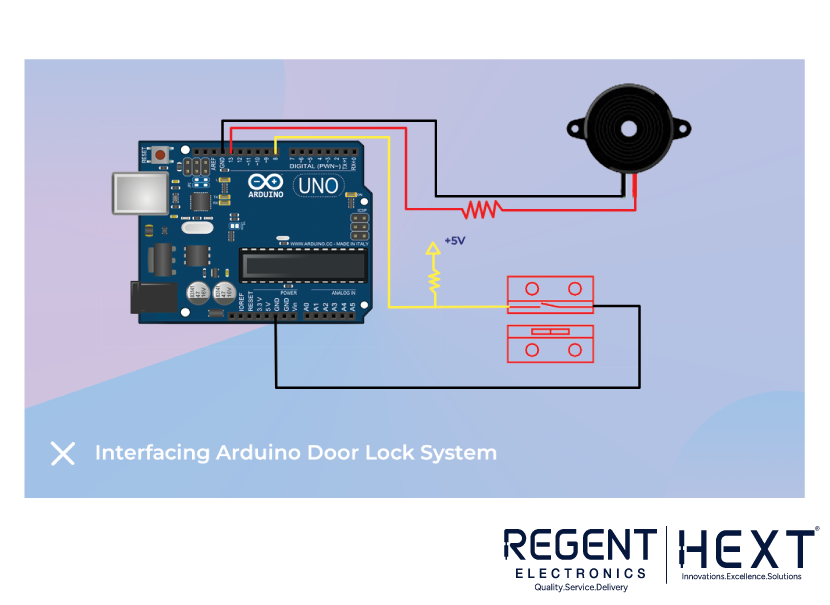
- One side of Reed Switch → GND
- Other side → Arduino D3 with 10kΩ pull-down resistor to GND
- LED +ve → D9 (with 220Ω resistor)
scss
CopyEdit
[ Reed Switch ] –(To GND & D3) with pull-down resistor
[ LED ] –(Positive)–> [ D9 Arduino ]
🧠 Code Logic:
cpp
CopyEdit
if (digitalRead(3) == LOW) {
digitalWrite(9, HIGH); // Door open
} else {
digitalWrite(9, LOW); // Door closed
}
✅ Application:
Use it as a door alert, cabinet safety system, or DIY security monitor.
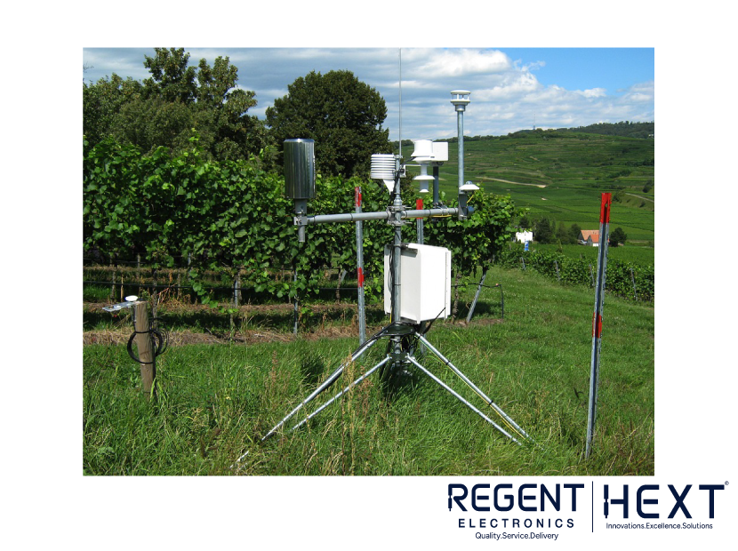
Project 4: 🌦️ Mini Weather Station Using DHT11
📦 Components Required:
- DHT11 Sensor
- 16×2 LCD Display with I2C Module
- Arduino Uno
- Jumper wires
🔧 Working:
The DHT11 reads temperature and humidity, and the data is shown on the LCD. The I2C module simplifies LCD wiring by reducing the number of pins required.
🔌 Circuit Connections:
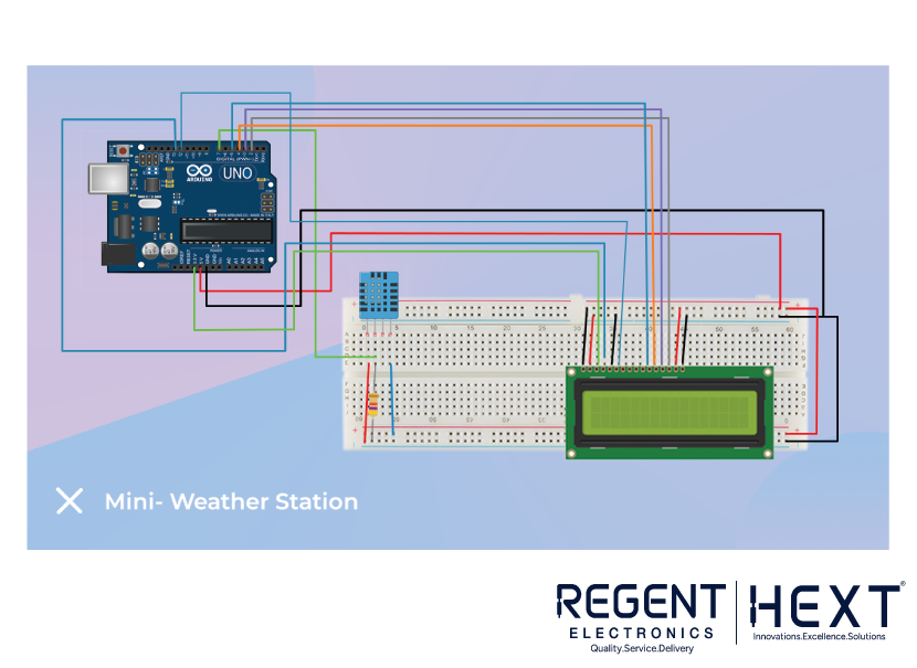
- DHT11 OUT → Arduino D2
- LCD SDA → A4, SCL → A5
- All VCC → 5V, GND → GND
scss
CopyEdit
[ DHT11 ] –(OUT)–> [ D2 Arduino ]
[ LCD I2C ] –(SDA/SCL)–> [ A4/A5 Arduino ]
🧠 Code Logic:
Use libraries: DHT.h and LiquidCrystal_I2C.h.
cpp
CopyEdit
lcd.setCursor(0, 0);
lcd.print(“Temp: “);
lcd.print(temp);
lcd.setCursor(0, 1);
lcd.print(“Hum: “);
lcd.print(humidity);
✅ Application:
Track room conditions or build an educational IoT weather station.
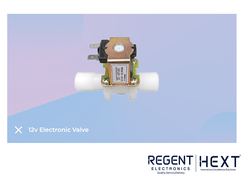
Project 5: 🌱 Smart IoT Plant Watering System

📦 Components Required:
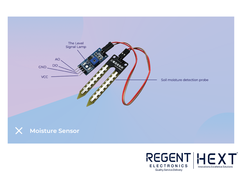
- Soil Moisture Sensor
- NodeMCU ESP8266 (Wi-Fi Module)
- Relay Module
- Small 5V Water Pump
- Jumper wires, mini pipe, power source
🔧 Working:
When the soil becomes dry, the moisture sensor detects low values. NodeMCU reads this and activates a water pump via relay. Optionally, data can be sent to the cloud (e.g., Blynk, MQTT).
🔌 Circuit Connections:
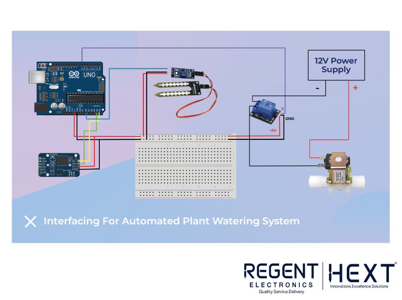
- Soil Sensor A0 → NodeMCU A0
- Relay IN → NodeMCU D1
- Pump +ve via Relay NO terminal
- All GNDs connected
scss
CopyEdit
[ Soil Moisture ] –(AO)–> [ A0 NodeMCU ]
[ Relay ] –(IN)–> [ D1 NodeMCU ]
[ Pump ] –(through Relay)–> Power
🧠 Code Logic:
cpp
CopyEdit
if (analogRead(A0) < threshold) {
digitalWrite(D1, HIGH); // Start pump
} else {
digitalWrite(D1, LOW); // Stop pump
}
✅ Application:
Great for automated home gardening and introducing IoT concepts.
🎁 Want Circuit Diagrams as Images?
Let me know if you’d like me to generate visual circuit diagrams (PNG/SVG) for any or all projects—great for blog embeds or printable guides.
🔚 Final Thoughts
With the Regent Electronics 37-in-1 Arduino Sensor Kit, you can start building real-world electronics projects without needing advanced tools. These five beginner projects teach key concepts in automation, sensing, and control—perfect for students, hobbyists, and tinkerers alike.