

How to Interface MPU6050 with Arduino | Regent Electronics
Introduction
Have you ever wondered how your mobile screen automatically adjusts when you move your smartphone vertically or horizontally? This is made possible with the help of an Inertial Measurement Unit (IMU) sensor like the MPU6050. In this blog, presented by Regent Electronics, we will explore the MPU6050 sensor, its working principles, and how to interface it with an Arduino board.
What is MPU6050?
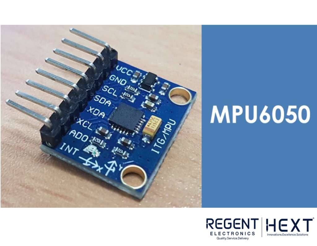
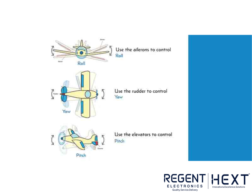
The MPU6050 is a six-axis motion tracking device that integrates a three-axis accelerometer and a three-axis gyroscope. It features a built-in Digital Motion Processor (DMP) that performs complex calculations, reducing the computational load on the microcontroller. This sensor provides precise motion data such as roll, pitch, yaw, angles, and orientation detection.
Key Features of MPU6050:
- 3-axis gyroscope
- 3-axis accelerometer
- 16-bit ADC conversion for each channel
- 1024-bit FIFO buffer
- Digital output temperature sensor
- Integrated Digital Motion Processor (DMP)
- Inbuilt temperature sensor
Pinout Configuration
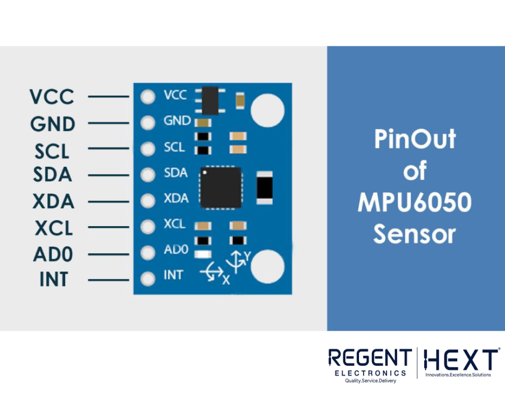
| Pin Name | Function |
| VCC | Power supply (5V/3.3V) |
| GND | Ground connection |
| SDA | Serial data input/output |
| SCL | Serial clock input |
| XDA | External sensor data line (optional) |
| XCL | External sensor clock line (optional) |
| AD0 | I2C slave address selection |
| INT | Interrupt pin for data indication |
Working Principle of MPU6050
How Does the Accelerometer Work?
The accelerometer in MPU6050 operates based on the piezoelectric effect. When the sensor is tilted, a tiny mass inside it shifts due to gravitational force, pressing against the piezoelectric crystals. This pressure generates an electrical signal, which is converted into digital motion data.
How Does the Gyroscope Work?
The gyroscope in MPU6050 works based on Coriolis acceleration. When the sensor rotates, vibrating elements inside it experience deflection, creating a proportional electrical signal. This signal is processed to determine angular velocity and orientation changes.
Interfacing MPU6050 with Arduino
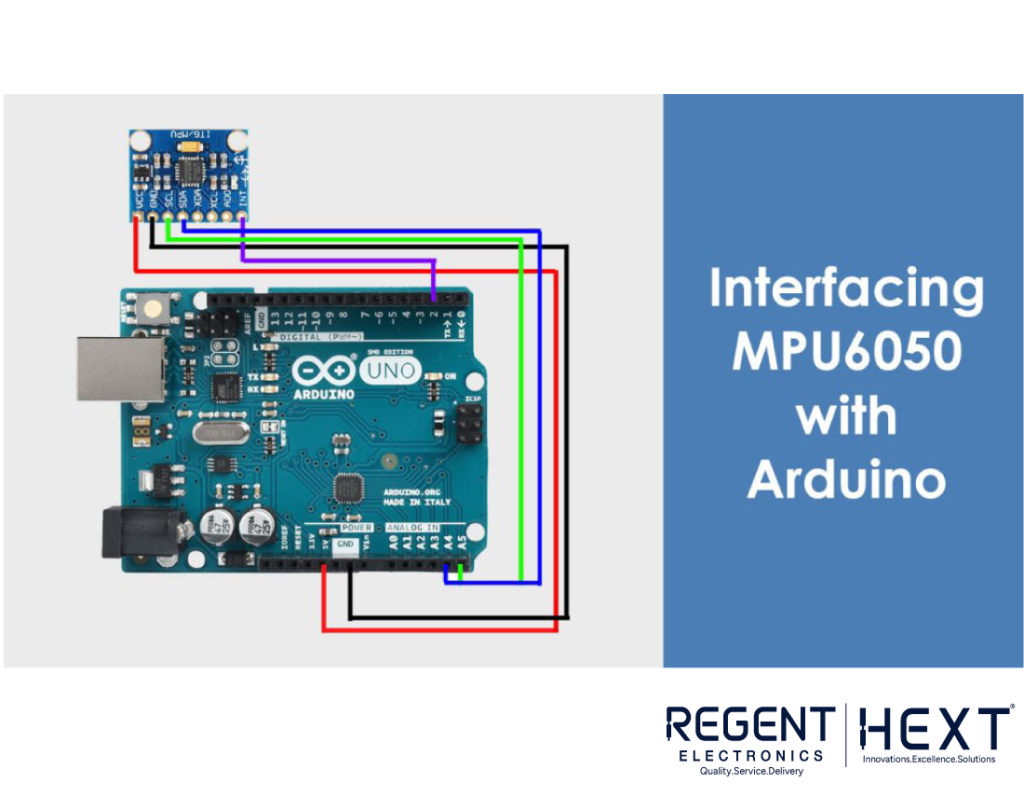
Since MPU6050 communicates using the I2C protocol, wiring it to an Arduino is straightforward. Below is the connection setup:
| Arduino Pin | MPU6050 Pin |
| 5V/3.3V | VCC |
| GND | GND |
| A5 | SCL |
| A4 | SDA |
| 2 | INT |
Programming the Arduino

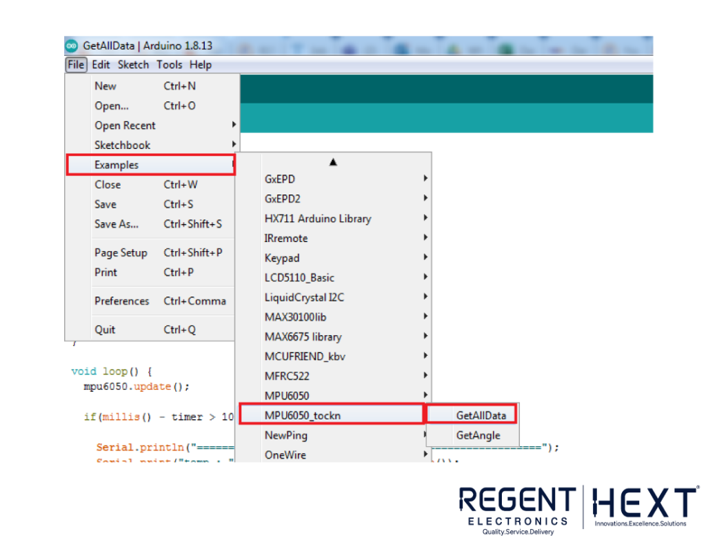
To obtain motion data from MPU6050, you need to install the Wire.h library.
#include <Wire.h>
const int MPU = 0x68; // MPU6050 I2C address
float AccX, AccY, AccZ;
float GyroX, GyroY, GyroZ;
float roll, pitch, yaw;
void setup() {
Serial.begin(19200);
Wire.begin();
Wire.beginTransmission(MPU);
Wire.write(0x6B);
Wire.write(0x00);
Wire.endTransmission(true);
}
void loop() {
Wire.beginTransmission(MPU);
Wire.write(0x3B);
Wire.endTransmission(false);
Wire.requestFrom(MPU, 6, true);
AccX = (Wire.read() << 8 | Wire.read()) / 16384.0;
AccY = (Wire.read() << 8 | Wire.read()) / 16384.0;
AccZ = (Wire.read() << 8 | Wire.read()) / 16384.0;
Serial.print(“AccX: “); Serial.print(AccX);
Serial.print(” AccY: “); Serial.print(AccY);
Serial.print(” AccZ: “); Serial.println(AccZ);
delay(500);
}
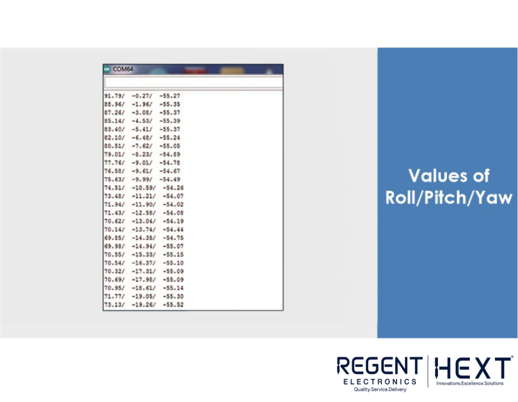
Upload this code to your Arduino, and you will receive real-time accelerometer and gyroscope values in the Serial Monitor.
Applications of MPU6050
MPU6050 is widely used in various fields, including:
- 3D remote controllers
- Wearable health and fitness trackers
- Drones and quadcopters for stabilization
- Robotic arm control
- Hand gesture recognition systems
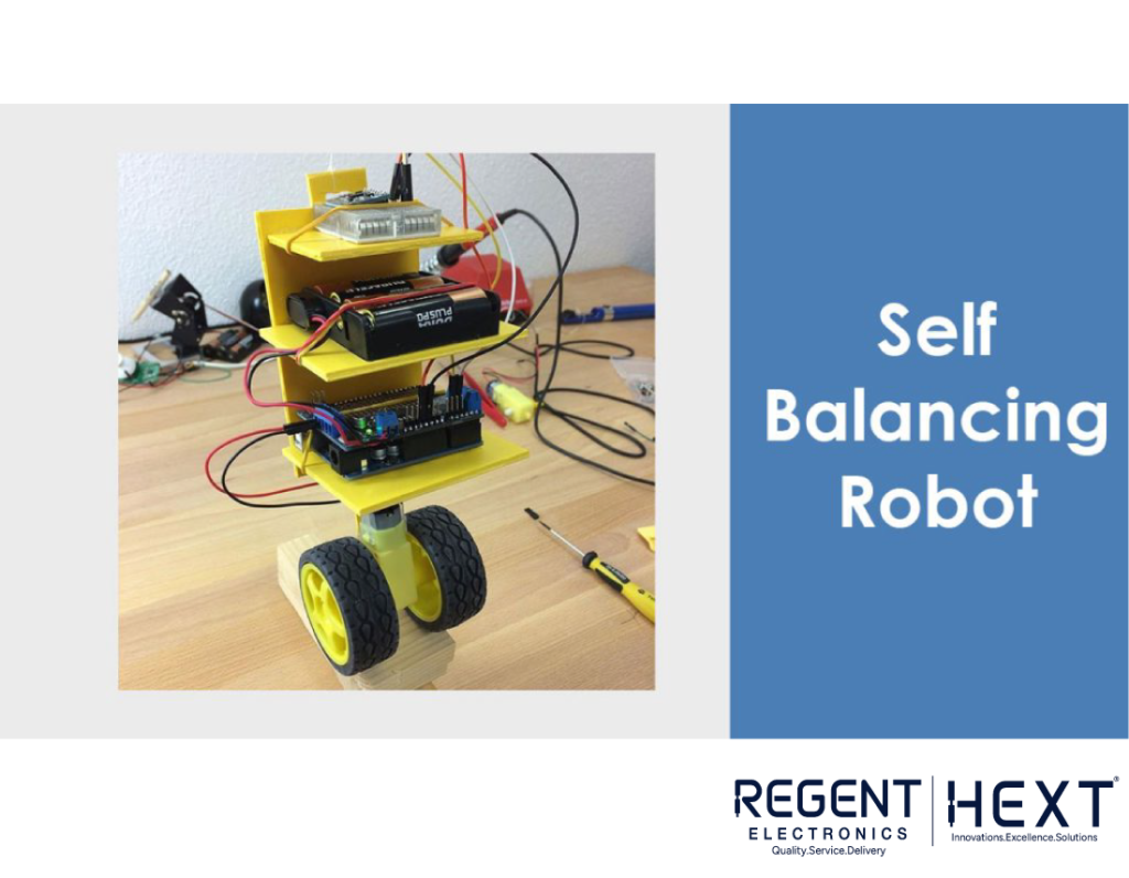
- Self-balancing robots
- Smartphones for automatic screen orientation
- Gimbal stabilization systems
Conclusion
The MPU6050 sensor is a crucial component in motion sensing applications. Its ability to measure acceleration and angular velocity makes it an essential part of drones, robots, and many smart devices. By integrating it with an Arduino, you can easily experiment with motion-based projects.
For more electronics tutorials and premium components, visit Regent Electronics! If you have any queries or need further assistance, feel free to leave a comment below!