

Interfacing Pulse Sensor with Arduino – Step by Step Guide with Code
A pulse sensor is a device that detects the pulse of a person. In this article, we will explore its working principle and how to interface it with an Arduino.
Introduction to Pulse Sensor

In today’s world, where technology is advancing rapidly, pulse sensors have gained popularity in consumer electronics. They are widely used in devices such as smart bands, smartwatches, and medical equipment. Monitoring pulse rate or heart rate at the right time can be crucial for saving lives.
This guide will cover various aspects of the pulse sensor, including its basic functionality, working principles, pinout, and interfacing with an Arduino board.
What is a Pulse Sensor?

A pulse sensor is an electronic component that detects a person’s pulse and transmits the data to a controller. Unlike other sensors that measure voltage or current, a pulse sensor measures heartbeats per minute when a fingertip is placed on it.
These sensors are commonly found in smartwatches and fitness bands, helping users track their heart rate continuously throughout the day. This data is essential for health-conscious individuals and athletes who require accurate pulse monitoring.
Working Principle of a Pulse Sensor
The working mechanism of a pulse sensor is straightforward. It consists of two sides: one with the actual sensor and the other with the circuit. The sensor side has an LED and an ambient light sensor.
When a user places their finger on the sensor, the LED emits light, and the ambient light sensor detects the variations in blood flow through the veins. These variations allow the calculation of heart rate. The circuit on the other side eliminates noise and amplifies the sensor data to make it readable for the Arduino.
Pinout and Connection with Arduino
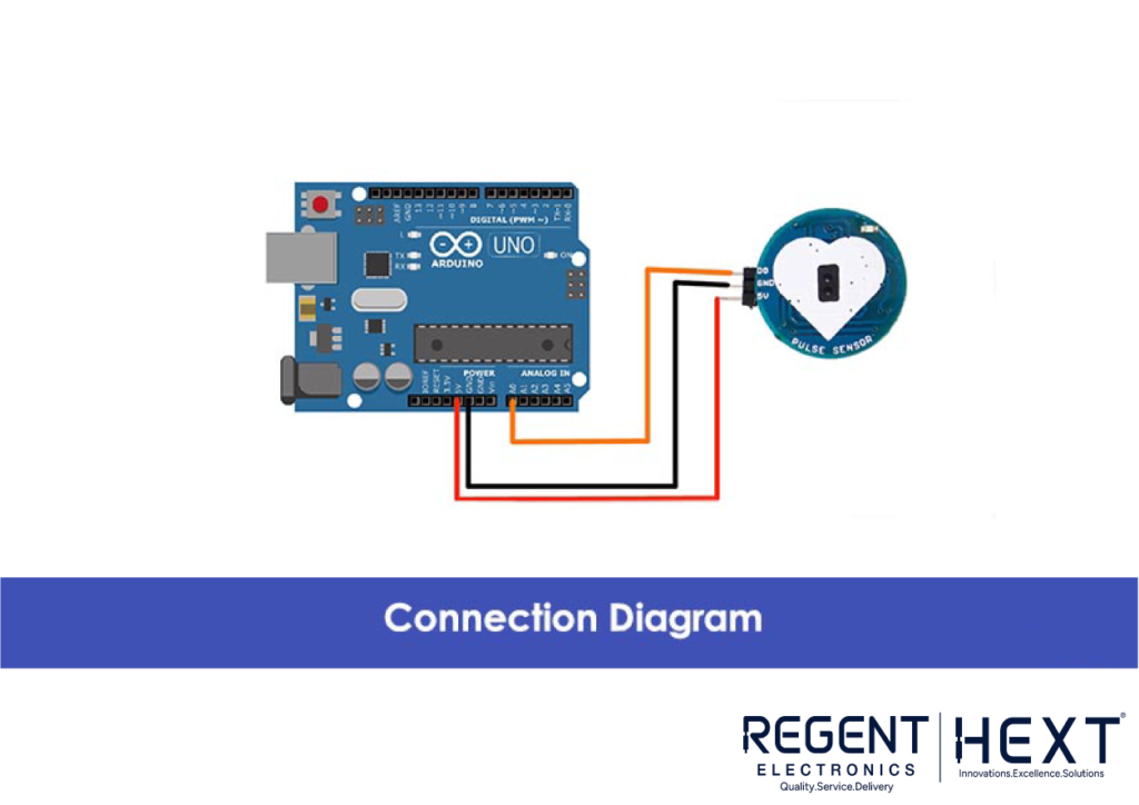
A pulse sensor typically has three pins:
- 5V – Power supply
- GND – Ground
- D0 – Analog data output
The sensor transmits analog data through the D0 pin, which can be connected to the Arduino’s analog pin. The sensor consumes only 4mA of current and has a built-in LED indicator to show its working status.
Connection Steps:
- Connect the 5V pin of the sensor to the 5V pin on the Arduino.
- Connect the GND pin of the sensor to the GND pin on the Arduino.
- Connect the D0 pin of the sensor to the A0 pin on the Arduino to read the analog signal.
Now, let’s move on to coding the Arduino to read data from the pulse sensor.
Arduino Code for Pulse Sensor
// Regent Electronics
// Pulse Sensor Arduino Code
int pulsePin = 0; // Pulse Sensor purple wire connected to analog pin A0
int blinkPin = 13; // LED blinks with each heartbeat
int fadePin = 8; // LED fades with each heartbeat
int fadeRate = 0; // PWM fade rate for LED
volatile int BPM; // Holds the heart rate value
volatile int Signal; // Raw analog data from sensor
volatile int IBI = 600; // Interval between beats
volatile boolean Pulse = false;
volatile boolean QS = false;
void setup() {
pinMode(blinkPin, OUTPUT);
pinMode(fadePin, OUTPUT);
Serial.begin(115200);
interruptSetup();
}
void loop() {
serialOutput();
if (QS == true) {
fadeRate = 255;
serialOutputWhenBeatHappens();
QS = false;
}
ledFadeToBeat();
delay(200);
}
void ledFadeToBeat() {
fadeRate -= 15;
fadeRate = constrain(fadeRate, 0, 255);
analogWrite(fadePin, fadeRate);
}
Final Words
In this article, we explored the fundamentals of pulse sensors, including their working principle and applications in health monitoring. We also demonstrated how to interface a pulse sensor with an Arduino board and write a simple code to monitor heart rate.
Pulse sensors are beneficial in both consumer electronics and medical applications. Whether you are a hobbyist or a professional, integrating pulse sensors into your projects can open doors to innovative health-monitoring solutions.
Let us know your thoughts in the comments! If you found this guide useful, share it with others. Happy coding!
Until Next Time! 🚀