

RFID and Password-Based Door Lock System Using Arduino
A Step-by-Step Guide to Building an RFID and Password-Based Door Lock System with Arduino
Introduction
In today’s digital world, security is a crucial aspect of both homes and businesses. Traditional mechanical locks are gradually being replaced by advanced digital security systems. One such technology is the RFID-based door lock system, which allows access using RFID tags and a password. This blog by Regent Electronics will guide you through creating an RFID and password-based door lock system using Arduino, enhancing security and automation.
Components Required for the Door Lock System
- Arduino Mega (or any compatible Arduino board)
- LCD1602 Parallel LCD Display (with Blue Backlight)
- MFRC522 RFID Reader & Tag
- 4×4 or 4×3 Keypad
- DC 12V Door Lock Solenoid
- 10k Potentiometer
- 5V Relay Module
- 5V to 12V Power Source (for DC Jack)
How the RFID-Based Door Lock System Works
This system operates using an RFID reader and a keypad. The RFID reader communicates with Arduino via the SPI protocol. Different Arduino boards have different SPI pins, so be sure to check your specific board.
- RFID Reader: Scans an RFID tag and sends the data to Arduino.
- Keypad Input: Allows the user to enter a password.
- LCD Display: Displays messages about access status.
- Relay Module & Door Lock: Controls the door lock solenoid.
When a valid RFID tag is scanned, the system prompts the user to enter a password. If both the tag and password are correct, the door unlocks. If incorrect credentials are entered, access is denied.
Connecting the Components with Arduino
1. Connecting the RFID Reader to Arduino Mega
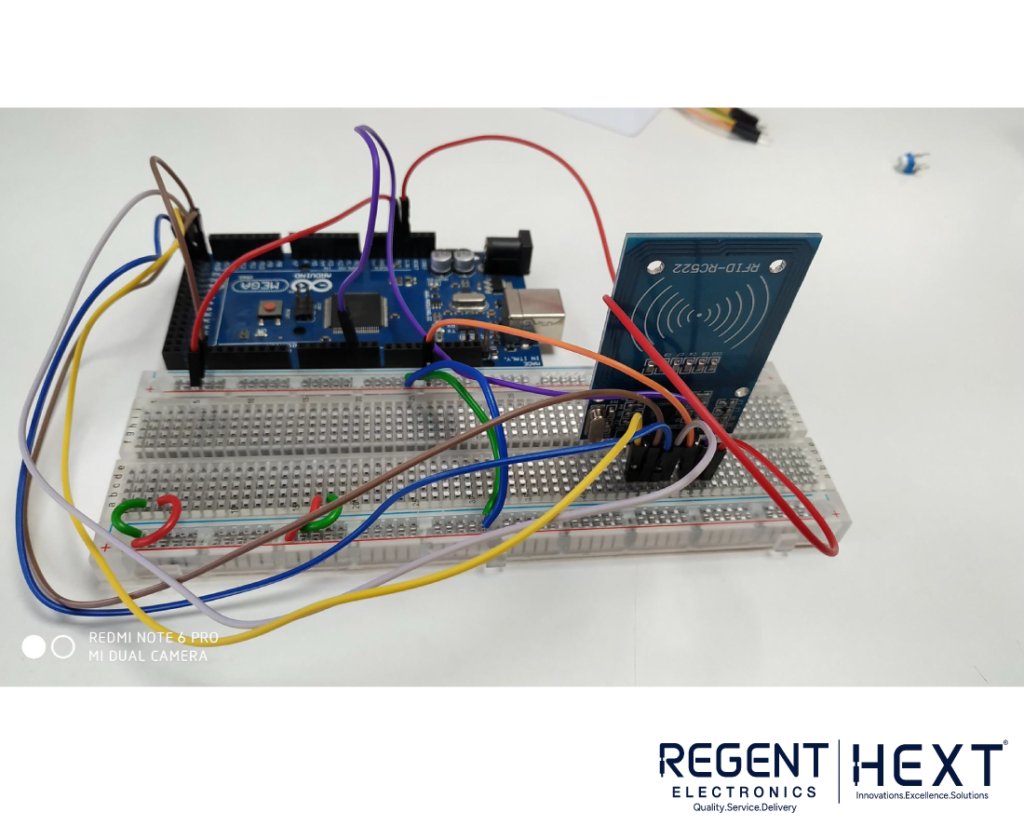
Use the following pin connections to interface the MFRC522 RFID Reader with Arduino Mega:
| RFID Reader Pin | Arduino Mega Pin |
| SDA | D9 |
| SCK | D52 |
| MOSI | D51 |
| MISO | D50 |
| IRQ | Not Required |
| GND | GND |
| RST | D8 |
| 3.3V | 3.3V |
2. Connecting the LCD Display to Arduino Mega
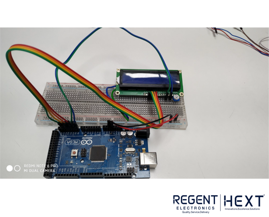
Use the following connections to interface the LCD1602 Display:
| LCD Pin | Arduino Mega Pin |
| RS | A8 |
| EN | A9 |
| D4 | A10 |
| D5 | A11 |
| D6 | A12 |
| D7 | A13 |
| VCC | 5V |
| GND | GND |
3. Connecting the Keypad to Arduino Mega

| Keypad Pin | Arduino Mega Pin |
| 1st | A0 |
| 2nd | A1 |
| 3rd | A2 |
| 5th | A3 |
| 6th | A4 |
| 7th | A5 |
4. Connecting the Relay Module and Door Lock Solenoid
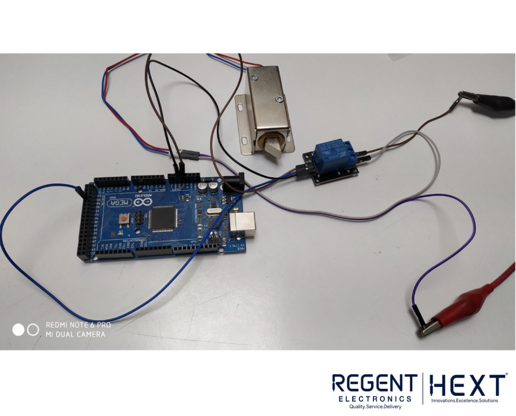
- Relay Module:
- VCC → 5V
- GND → GND
- Signal → Pin 49
- Door Lock Solenoid: Connect to the relay module output
Software and Programming
To program your Arduino, download the required software and libraries:
- Arduino IDE
- SPI Library
- Software Serial Library
- Keypad Library
- MFRC522 RFID Library
Below is the Arduino code for the RFID-based door lock system:
#include <MFRC522.h>
#include <Keypad.h>
#include <SoftwareSerial.h>
#include <SPI.h>
#include <LiquidCrystal.h>
MFRC522 mfrc522(53, 5); // RFID Module Pins
LiquidCrystal lcd(A8, A9, A10, A11, A12, A13);
#define Doorrelay 49
char initial_password[4] = {‘1’, ‘2’, ‘3’, ‘4’};
String tagUID = “19 47 64 C1”;
char password[4];
boolean RFIDMode = true;
boolean NormalMode = true;
char key_pressed = 0;
uint8_t i = 0;
const byte rows = 3, columns = 3;
char hexaKeys[rows][columns] = {{‘1’, ‘2’, ‘3’}, {‘4’, ‘5’, ‘6’}, {‘7’, ‘8’, ‘9’}};
byte row_pins[rows] = {A0, A1, A2};
byte column_pins[columns] = {A3, A4, A5};
Keypad keypad_key = Keypad(makeKeymap(hexaKeys), row_pins, column_pins, rows, columns);
void setup() {
Serial.begin(9600);
pinMode(Doorrelay, OUTPUT);
lcd.begin(16, 2);
SPI.begin();
mfrc522.PCD_Init();
lcd.print(“Scan Your TAG”);
}
void loop() {
if (RFIDMode) {
if (!mfrc522.PICC_IsNewCardPresent() || !mfrc522.PICC_ReadCardSerial()) return;
String tag = “”;
for (byte j = 0; j < mfrc522.uid.size; j++) {
tag.concat(String(mfrc522.uid.uidByte[j], HEX));
}
tag.toUpperCase();
if (tag.substring(1) == tagUID) {
lcd.clear();
lcd.print(“Enter Password:”);
RFIDMode = false;
} else {
lcd.clear();
lcd.print(“Access Denied”);
delay(3000);
lcd.print(“Scan Your TAG”);
}
} else {
key_pressed = keypad_key.getKey();
if (key_pressed) password[i++] = key_pressed;
if (i == 4) {
if (!strncmp(password, initial_password, 4)) {
lcd.clear();
lcd.print(“Access Granted”);
digitalWrite(Doorrelay, LOW);
delay(5000);
digitalWrite(Doorrelay, HIGH);
} else {
lcd.clear();
lcd.print(“Wrong Password”);
}
i = 0;
RFIDMode = true;
lcd.print(“Scan Your TAG”);
}
}
}
Conclusion

This project provides a simple yet effective way to implement a secure RFID and password-based door lock system using Arduino. By following this guide from Regent Electronics, you can enhance your home or office security with a cost-effective and efficient system. Try it out today and build your own smart access control system!
For more tutorials and electronic projects, stay tuned to Regent Electronics!