
Interfacing IR Sensor With STM32 Discovery Board
Introduction
STM32 boards come with 23 interrupt sources, making them highly efficient for real-time applications. In this article, we will explore how the STM32 handles interrupts and how to interface an Infrared (IR) Sensor with the STM32 Discovery Board. This guide is especially useful for beginners looking to understand GPIO pin usage and interrupt handling in STM32 programming.
Components Required
- STM32F407 Discovery Board
- Infrared Sensor
- LEDs
- Breadboard
- Jumper Wires
- USB Type-A to Mini-B Cable
Interfacing Diagram
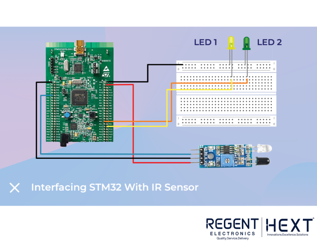
The diagram below illustrates the connection between the IR sensor and the STM32 Discovery Board. The PA1 pin is used to introduce an interrupt when the IR sensor detects an obstacle. The LED connected to PD1 indicates the interrupt status.
Pin Configuration
- LED1 – PD0 (Pin 0 of Port D)
- LED2 – PD1 (Pin 1 of Port D)
- IR (5V) – 5V of STM32 Board
- IR (GND) – GND of STM32 Board
- IR (Dout) – PA1 (Pin 1 of Port A)
Software Setup
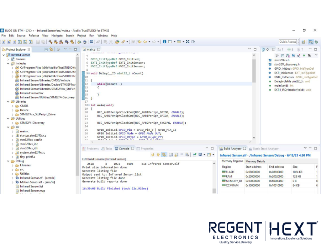

To program the STM32 Discovery Board, we will use Atollic TrueStudio. Follow these steps to create and deploy the project:
- Install Atollic TrueStudio.
- Create a new C project: File > New Project > C Project.
- Write the code.
- Save the project.
- Build and compile the project.
- Debug the code by pressing the resume button to run it on the STM32 Board.
Code Implementation
STM32F GPIO pins are classified into different ports (Port A, Port B, Port C, etc.). By default, these ports are inactive and must be enabled before use.
#include “stm32f4xx.h”
#include “stm32f4_discovery.h”
GPIO_InitTypeDef GPIO_InitLed;
EXTI_InitTypeDef EXTI_InitSensor;
NVIC_InitTypeDef NVIC_InitSensor;
void Delay(__IO uint32_t nCount) {
while(nCount–) {}
}
int main(void) {
RCC_AHB1PeriphClockCmd(RCC_AHB1Periph_GPIOD, ENABLE);
RCC_AHB1PeriphClockCmd(RCC_AHB1Periph_GPIOA, ENABLE);
RCC_AHB2PeriphClockCmd(RCC_APB2Periph_SYSCFG, ENABLE);
GPIO_InitLed.GPIO_Pin = GPIO_Pin_0 | GPIO_Pin_1;
GPIO_InitLed.GPIO_Mode = GPIO_Mode_OUT;
GPIO_InitLed.GPIO_OType = GPIO_OType_PP;
GPIO_InitLed.GPIO_PuPd = GPIO_PuPd_NOPULL;
GPIO_InitLed.GPIO_Speed = GPIO_Speed_50MHz;
GPIO_Init(GPIOD, &GPIO_InitLed);
GPIO_InitLed.GPIO_Pin = GPIO_Pin_1;
GPIO_InitLed.GPIO_Mode = GPIO_Mode_IN;
GPIO_InitLed.GPIO_PuPd = GPIO_PuPd_DOWN;
GPIO_Init(GPIOA, &GPIO_InitLed);
SYSCFG_EXTILineConfig(EXTI_PortSourceGPIOA, EXTI_PinSource1);
EXTI_InitSensor.EXTI_Line = EXTI_Line1;
EXTI_InitSensor.EXTI_Mode = EXTI_Mode_Interrupt;
EXTI_InitSensor.EXTI_Trigger = EXTI_Trigger_Rising;
EXTI_InitSensor.EXTI_LineCmd = ENABLE;
EXTI_Init(&EXTI_InitSensor);
NVIC_PriorityGroupConfig(NVIC_PriorityGroup_1);
NVIC_InitSensor.NVIC_IRQChannel = EXTI1_IRQn;
NVIC_InitSensor.NVIC_IRQChannelPreemptionPriority = 0;
NVIC_InitSensor.NVIC_IRQChannelSubPriority = 0;
NVIC_InitSensor.NVIC_IRQChannelCmd = ENABLE;
NVIC_Init(&NVIC_InitSensor);
while (1) {
GPIO_WriteBit(GPIOD, GPIO_Pin_0, Bit_SET);
Delay(16800000);
GPIO_WriteBit(GPIOD, GPIO_Pin_0, Bit_RESET);
Delay(16800000);
}
}
void EXTI1_IRQHandler(void) {
if(EXTI_GetITStatus(EXTI_Line1) != RESET) {
GPIO_WriteBit(GPIOD, GPIO_Pin_1, Bit_SET);
Delay(33600000);
GPIO_WriteBit(GPIOD, GPIO_Pin_1, Bit_RESET);
EXTI_ClearITPendingBit(EXTI_Line1);
}
}
Output
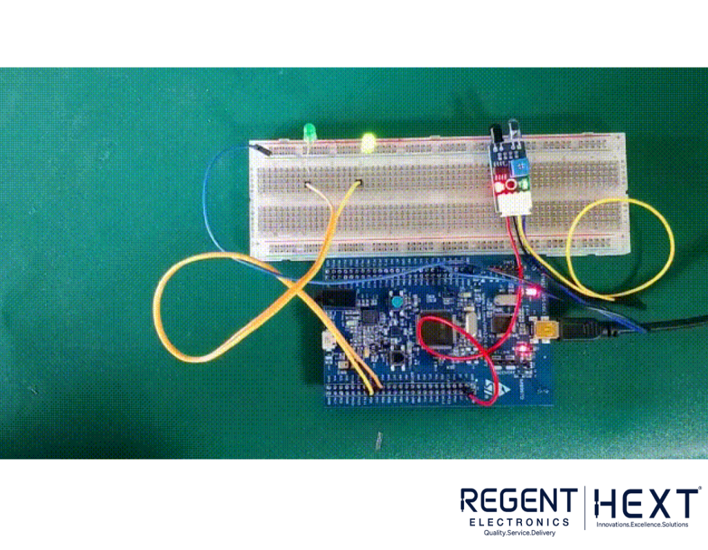
Upon successfully running the code, the LED will blink when the IR sensor detects an obstacle. The interrupt will be triggered, and the LED at PD1 will turn on momentarily before turning off again.
Conclusion
This tutorial demonstrated how to interface an IR sensor with the STM32 Discovery Board and handle interrupts efficiently. By integrating real-time obstacle detection, this project serves as a foundation for more complex automation applications. If you have any questions or suggestions, feel free to leave a comment!