
AD8232 Heart Rate Monitor: A Detailed Guide with Arduino Interfacing
Introduction
The AD8232 Heart Rate Monitor is a cost-effective ECG sensor module that measures the heart’s electrical activity. In this guide, we will explore its working principles, applications, and how to interface it with an Arduino using appropriate code.
Understanding the AD8232 Heart Rate Monitor
The AD8232 ECG sensor module is designed to measure electrocardiography (ECG), also known as EKG, which records electrical changes in the heart. ECG is a non-invasive method for detecting heart rhythm irregularities and monitoring cardiovascular health. This technology plays a crucial role in diagnosing potential heart conditions and preventing cardiac-related complications.
How ECG Works
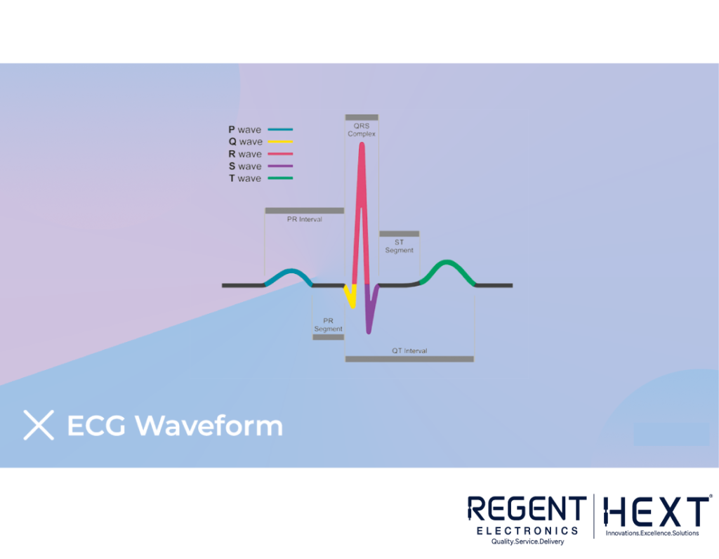
Electrocardiography captures the electrical activity of the heart using conductive electrodes attached to the skin. The ECG waveform comprises different segments:
- P Wave: Generated by the sinoatrial (SA) node, indicating atrial depolarization.
- QRS Complex: Representing ventricular depolarization through the atrioventricular (AV) node.
- T Wave: Indicates ventricular repolarization.
By analyzing these waveforms, medical professionals can detect heart abnormalities, potential heart attacks, and irregular heartbeats.
Applications of ECG Monitoring
- Diagnosing high blood pressure effects on the heart
- Detecting cholesterol-induced heart blockage
- Identifying past or potential heart attacks
- Monitoring abnormal heart rhythms
- Evaluating cardiac health for fitness tracking
Overview of AD8232 Heart Rate Monitor Sensor
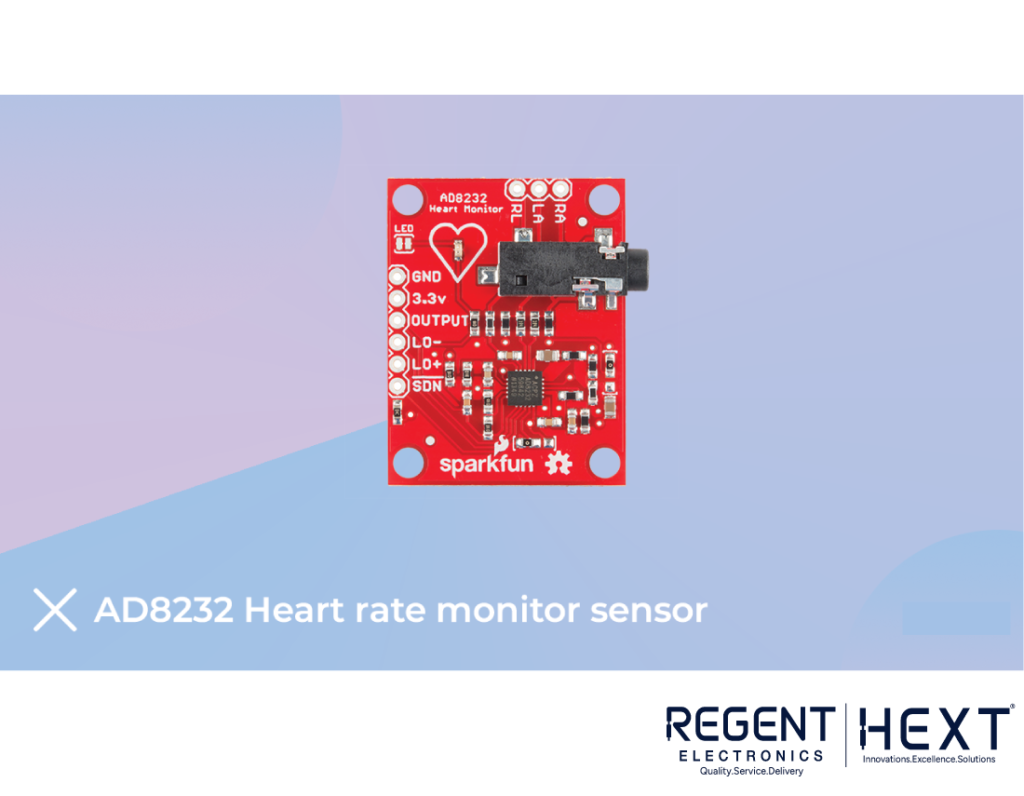
The AD8232 is a single-lead ECG sensor that helps obtain clean heart signals for monitoring purposes. It filters and amplifies weak bio-potential signals, even in noisy conditions caused by movement or remote electrode placement.
Features of AD8232
- Operating Voltage: 3.3V
- Analog Output
- Lead-Off Detection
- Integrated Signal Conditioning
- LED Indicator
- 3.5mm Jack for Biomedical Pad Connection
Components Required for Interfacing
- AD8232 ECG sensor module
- Arduino Uno
- Power cable
- Breadboard
- Jumper wires
Interfacing AD8232 ECG Sensor with Arduino
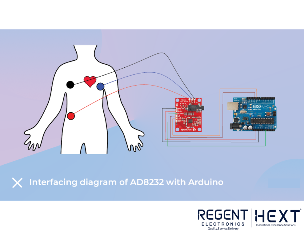
Circuit Connections
- GND of AD8232 → GND of Arduino
- 3.3V of AD8232 → 3.3V of Arduino
- OUTPUT of AD8232 → A0 of Arduino
- LO- of AD8232 → Pin 11 of Arduino
- LO+ of AD8232 → Pin 10 of Arduino
- SDN pin left unconnected
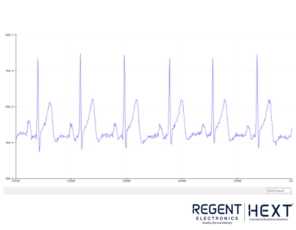
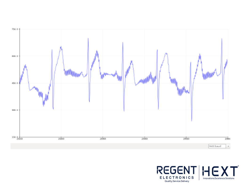
Code for ECG Signal Processing
Before uploading the code, ensure that the Arduino IDE is installed.
void setup() {
Serial.begin(9600); // Initialize serial communication
pinMode(10, INPUT); // Setup for leads-off detection (LO+)
pinMode(11, INPUT); // Setup for leads-off detection (LO-)
}
void loop() {
if ((digitalRead(10) == 1) || (digitalRead(11) == 1)) {
Serial.println(“!”); // Leads-off detected
} else {
Serial.println(analogRead(A0)); // Print ECG signal
}
delay(1); // Prevent data saturation
}
Sensor Electrode Placement Guide
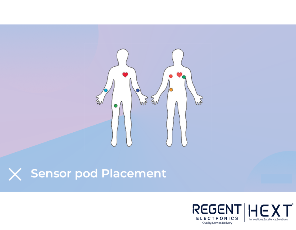
For accurate results, place the sensor electrodes in the following positions:
- Red (RA): Right Arm
- Yellow (LA): Left Arm
- Green (RL): Right Leg
Positioning the electrodes close to the heart enhances the quality of the ECG signal.
Conclusion
The AD8232 ECG sensor module is an affordable and efficient way to monitor heart health. Whether you are a fitness enthusiast, a hobbyist, or someone interested in biomedical applications, this module allows you to track heart activity with ease. If you found this guide helpful, don’t forget to share it!
Stay healthy and keep monitoring your heart rate with Regent Electronics!