

What are Pull-up and Pull-down Resistors?
Introduction
In this article, we will explore the concept of pull-up and pull-down resistors, which play a crucial role in digital electronic circuits. These resistors help in maintaining proper voltage levels and ensuring that input signals do not fluctuate randomly when there is no input condition.
Understanding Pull-up and Pull-down Resistors
In any microcontroller-based embedded system, such as Arduino, pull-up and pull-down resistors manage input and output signals for communication with external hardware devices through General Purpose Input Output (GPIO) pins. Using these resistors ensures that the system reads either a ‘high’ or ‘low’ state, preventing a floating impedance state when no signal is present.
Pull-up Resistors
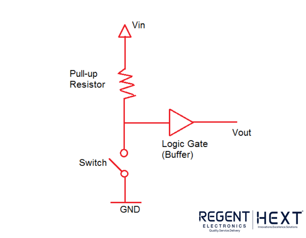
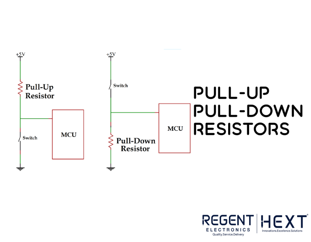
A pull-up resistor is used to ensure that a wire is pulled to a high logical level in the absence of an input signal. These resistors are connected between the voltage supply and the appropriate pin to define the input or output voltage when no driving signal is present.
How Pull-up Resistors Work
When the switch is open, the voltage at the gate input is pulled up to the level of the input voltage. When the switch is closed, the input voltage at the gate is directly connected to the ground.
Pull-up Resistor Setup
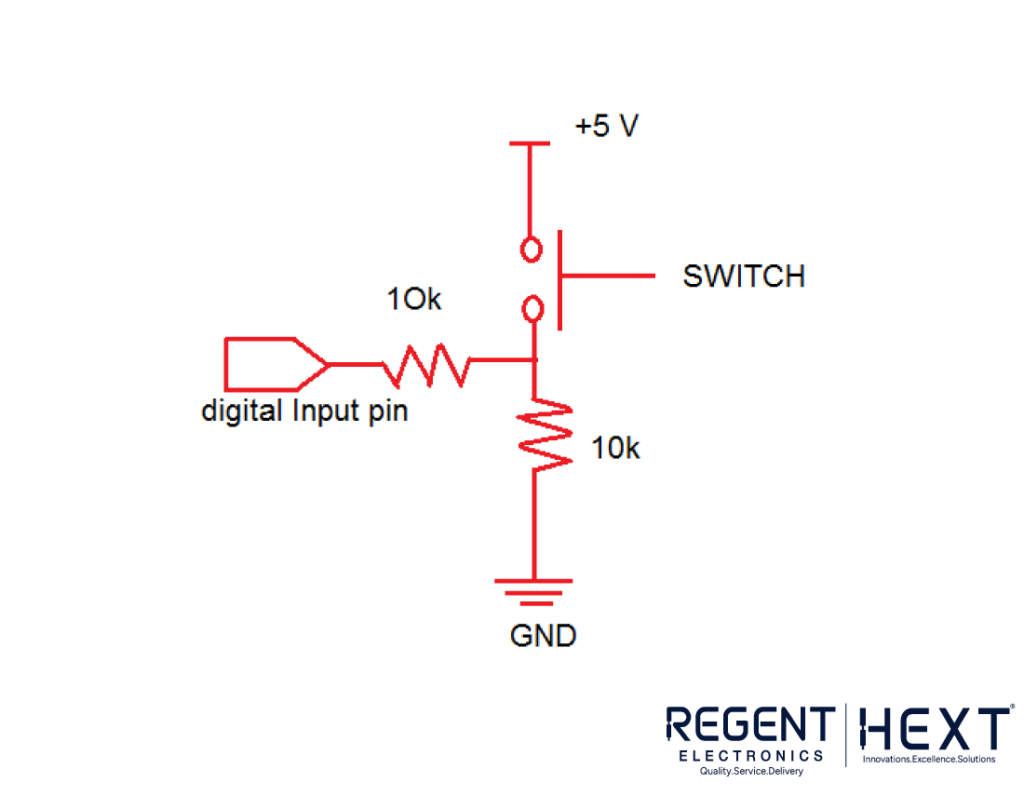
In a typical pull-up resistor setup, a fixed-value resistor is used to connect the voltage supply to a specific pin in the digital logic circuit. This ensures controlled voltage levels when the switch is open. Without a pull-up resistor, the circuit may experience a short circuit due to a direct connection between the pin and VCC or ground.
Using Ohm’s law, a small current flows from the source through the resistor and switch before reaching the ground, preventing circuit damage.
Pull-down Resistors
Pull-down resistors ensure that inputs to logic systems remain at expected logic levels when external devices are disconnected. They hold the logic signal close to zero volts (0V) when no active connections are present, preventing undefined states.
How Pull-down Resistors Work
Pull-down resistors pull the input voltage down to ground when no signal is present. The resistance value must be larger than the impedance of the logic circuit. Otherwise, the input voltage would be constantly low, regardless of switch position.
Pull-down Resistor Setup
Similar to pull-up resistors, pull-down resistors actively control voltage levels when the switch is open. However, instead of pulling the pin to a high value, they pull it to a low value.
When the switch is open, the resistor connected to ground ensures that the logic level remains low. When the switch is closed, the input voltage rises to Vin, enabling a controlled logic level transition.
Choosing the Ideal Resistance Values
When selecting a pull-up or pull-down resistor, two key considerations must be taken into account:
- Power Dissipation: The resistor value controls the current flow. If the resistance is too low, excessive current flows through the circuit, leading to unnecessary power consumption and potential overheating.
- Pin Voltage Control: The resistor value also determines the voltage on the input pin. If the resistance is too high, the input voltage may become unstable due to leakage currents.
For pull-up resistors:
- The resistor should be at least 10 times smaller than the value of the input pin impedance.
- For 5V logic devices, a typical pull-up resistor value ranges between 1kΩ and 5kΩ.
- For switch and resistive sensor applications, the typical pull-up resistor value ranges between 1kΩ and 10kΩ.
For pull-down resistors:
- The resistance should be larger than the impedance of the logic circuit to avoid excessive voltage drop.
Conclusion
In summary, pull-up and pull-down resistors are essential in digital circuits to maintain stable logic levels. They prevent undefined states and ensure efficient operation of microcontrollers and other electronic components. By choosing the right resistance values, power consumption can be minimized, and circuit reliability can be enhanced.
If you found this article helpful, feel free to share it with your peers and leave any questions or feedback in the comments. Stay tuned for more informative content from Regent Electronics!