
LCD Interfacing with Arduino | Regent Electronics
Introduction
In many embedded system projects, real-time monitoring of processes is essential. While serial monitors help in debugging, they can be time-consuming. A better alternative is to interface an LCD with an Arduino board. This blog will guide you through the process of interfacing a 16×2 LCD display with an Arduino board effectively.
What is an LCD Display?
LCD stands for Liquid Crystal Display. It operates by using liquid crystals that allow backlight to pass through when voltage is applied. This creates visible characters or images on the screen.
Why Use an LCD in Arduino Projects?
An LCD display enhances user experience by providing real-time feedback and information about system processes. It is commonly used in appliances such as coffee makers, where it displays options and machine status.
While various display options like seven-segment displays, TFT LCDs, and OLEDs are available, a 16×2 LCD is a budget-friendly and effective choice.
16×2 LCD Display Pinout Details
Power Pins:
- VCC and GND: Powers the LCD via the Arduino.
- VEE: Adjusts display brightness using a potentiometer.
- LED+ and LED-: Control the LCD backlight.
Control Pins:
- RS (Register Select): Determines whether data is interpreted as a command or display content.
- R/W (Read/Write): Controls read/write operations (set to LOW for write mode).
- EN (Enable): Activates the LCD module.
Data Pins:
- DB0-DB7: Transmit data or commands to the LCD.
How to Interface LCD with Arduino
Components Required:
Hardware:
- Arduino Board
- 16×2 LCD Display
- Potentiometer (for brightness adjustment)
Software:
- Arduino IDE
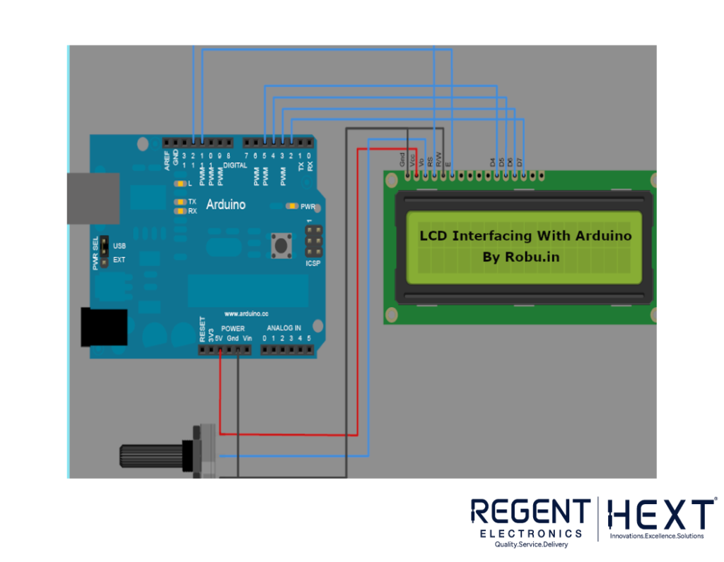
Circuit Connections:
- Powering the LCD: Connect VCC and GND of the LCD to the corresponding pins on the Arduino.
- Contrast Control: Connect VEE to a potentiometer output (or directly to 3.3V if a potentiometer is unavailable).
- Backlight Power: Connect LED+ to VCC and LED- to GND.
- Data Pins: Connect DB4 to DB7 to Arduino pins 5, 4, 3, and 2.
- Control Pins: Connect RS and E to D11 and D12, while R/W is connected to GND (write mode enabled).
Arduino Code for LCD
#include <LiquidCrystal.h>
LiquidCrystal lcd(12, 11, 5, 4, 3, 2); // Define LCD interface pins
void setup() {
lcd.begin(16, 2); // Initialize the LCD
lcd.setCursor(0,0);
lcd.print(“LCD Tutorial”); // Display text
lcd.setCursor(5,1);
lcd.print(“HELLO WORLD”);
}
void loop() {
// Your Code
}
Explanation of Key Functions:
- #include <LiquidCrystal.h>: Includes the LCD library.
- lcd.begin(16,2): Initializes communication with a 16×2 LCD.
- lcd.print(“…”): Displays text on the LCD.
- lcd.setCursor(x,y): Sets the cursor position on the LCD.
Scrolling Text on 16×2 LCD with Arduino
To scroll text across the LCD screen, use the following code:
#include <LiquidCrystal.h>
LiquidCrystal lcd(12, 11, 5, 4, 3, 2);
int speed = 0;
void setup() {
lcd.begin(16, 2); // Initialize LCD
lcd.setCursor(0,1);
lcd.print(“Tutorial by Regent Electronics”); // Scrolling Text
}
void loop() {
for(speed=0; speed<2; speed++) {
lcd.scrollDisplayRight(); // Scroll display right
}
delay(500); // Adjust speed of scrolling
}
Conclusion
In this blog, we covered the fundamentals of LCD interfacing with Arduino, including circuit connections, key functions, and scrolling text implementation. Using an LCD in your projects improves user interaction and provides real-time monitoring.
If you have any questions, feel free to drop them in the comments below!