

DIY Clap Switch Using CD4017 Decade Counter IC: A Step-by-Step Guide
If you’re looking to create an innovative and practical project, a DIY Clap Switch using the CD4017 decade counter IC is a great choice. This versatile circuit can be used in various applications, including turning on lights, activating devices, or even controlling curtain sliders. Ideal for assisting individuals with mobility impairments, this switch offers the convenience of hands-free operation without the need for a remote or battery changes.
Components Required
To build this project, you’ll need:
- CD4017 IC
- Relay
- Connecting Wires
- Transistor (e.g., BC547)
- Resistors
- Capacitors
- Power Supply
- Breadboard
- Condenser Microphone
What is the CD4017 IC?
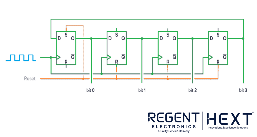
The CD4017 is a decade counter integrated circuit (IC) with ten decoded outputs, labeled Q0 through Q9. Each rising clock pulse increments the counter, sequentially activating one output pin. Once the counter reaches Q9, it resets to Q0 on the next pulse.
Key Features of the CD4017
- It operates in a Johnson counter mode, making it efficient with only five flip-flops and additional logic gates.
- Commonly used in LED chasers, frequency dividers, music sequencers, and alarms.
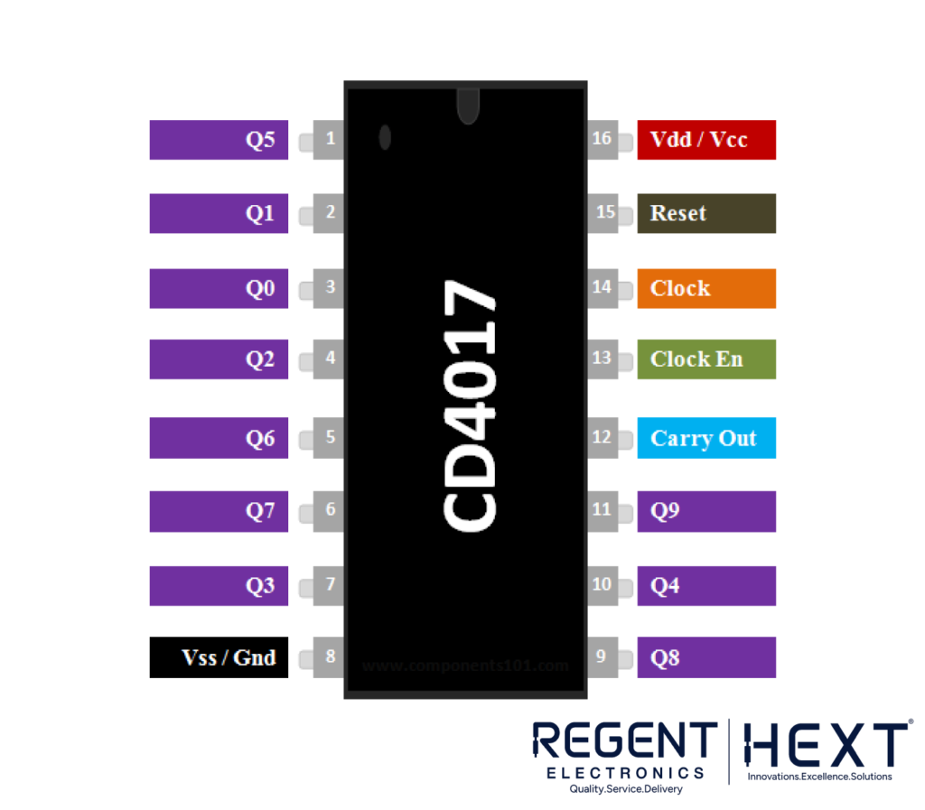
CD4017 Pinout Description
- CLK (Clock Input): Increments the counter when it transitions from low to high.
- Q0–Q9: Outputs corresponding to the counter value, which activate sequentially.
- Clock Inhibit (CI): Stops the counter when set high. To enable counting, keep it low.
- Carry Out (CO): High for five clock pulses when the counter reaches Q9, allowing cascading of multiple counters.
- VDD: Connect to the positive power supply (+3V to +15V).
- GND: Connect to the negative power supply.
Working of the Clap Switch Circuit
- Clap Detection:
The condenser microphone detects the clap sound and converts it into an electrical pulse. - Signal Amplification:
The BC547 transistor amplifies the weak electrical signal from the microphone. - Pulse Input to CD4017:
The amplified signal is fed to the CLK pin of the CD4017 IC. - State Transition:
With each high pulse on the CLK pin, the output pin (Q0–Q9) changes state sequentially. - Relay Control:
- When PIN 2 of the IC becomes HIGH, it activates a second transistor, which in turn activates the relay.
- The connected load (e.g., light or device) switches ON.
- Upon detecting the next clap, the output changes state, turning the relay and load OFF.
Circuit Diagram and Implementation
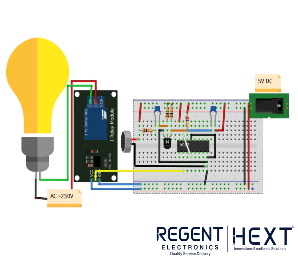
The circuit diagram showcases how components are connected:
- The condenser microphone acts as the sound sensor.
- A BC547 transistor amplifies the microphone’s output.
- The amplified signal drives the CD4017 IC.
- A relay module handles the load switching.
Note: Ensure proper placement of components on the breadboard for a stable connection.
Benefits of Using a Clap Switch
- Convenience: Hands-free control for lights and appliances.
- Energy Efficiency: Eliminates the need for remote control batteries.
- Accessibility: Ideal for individuals with mobility challenges.
This step-by-step guide provides an easy way to build a DIY Clap Switch using the CD4017 IC. Not only is it a fun project, but it also introduces you to basic electronics and IC functionality. Start building today and bring convenience to your daily life!