
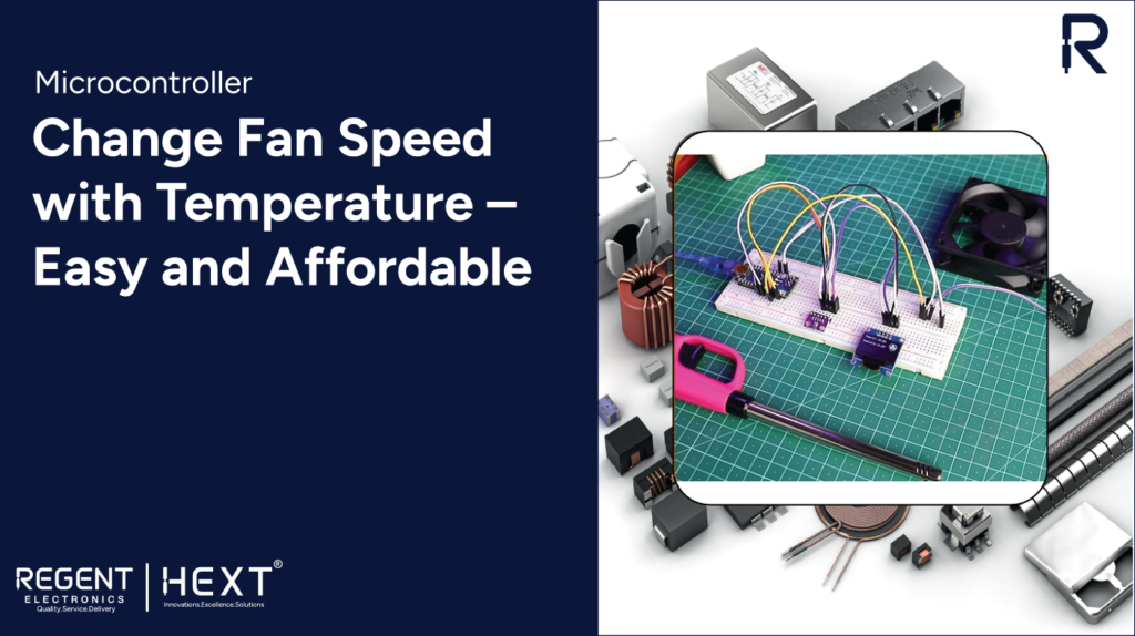
Control Fan Speed Based on Temperature with Arduino and BME280
Keeping electronic components cool is crucial for efficiency and longevity. In this blog, we’ll explore an easy and cost-effective way to regulate fan speed based on temperature variations using the BME280 sensor and an Arduino board.
How Does the Fan Speed Change?
The project utilizes a temperature sensor to monitor ambient temperature. An Arduino Nano processes this data and adjusts the fan speed accordingly by controlling a transistor that regulates power to the fan. For higher efficiency, a MOSFET can be used instead of a BJT transistor, especially for higher current applications.
What is Arduino?
Arduino is an open-source electronics platform that combines hardware and software to facilitate interactive projects. It can process inputs from various sensors and control outputs such as motors, LEDs, and more.
For this project, we are using an Arduino Nano, but other Arduino boards can also be used. Some key specifications of the Arduino Nano include:
- Microcontroller: ATmega328
- SRAM: 2 KB
- Digital I/O Pins: 22
- PWM Pins: 6
- Analog Input Pins: 8
- Clock Speed: 16 MHz
What is BME280?
The BME280 sensor is a high-precision module capable of measuring temperature, humidity, and atmospheric pressure. It is widely used for environmental monitoring and weather-based applications due to its broad operating range from -40°C to +85°C.
Transistor and Fan
We use a 5V fan (80×80 mm) along with a BC547 transistor to control the fan speed. The transistor acts as a switch that modulates the voltage supplied to the fan, allowing speed regulation based on temperature readings.
Required Hardware
- Arduino Nano
- BME280 Sensor
- SSD1306 OLED Display
- 5V Fan
- BC547 Transistor
- Jumper Wires
- Breadboard
- Lighter (for testing purposes)
Required Software
- Arduino IDE
- Adafruit Libraries for SSD1306 display and BME280 sensor
Circuit Diagram and Hardware Interfacing
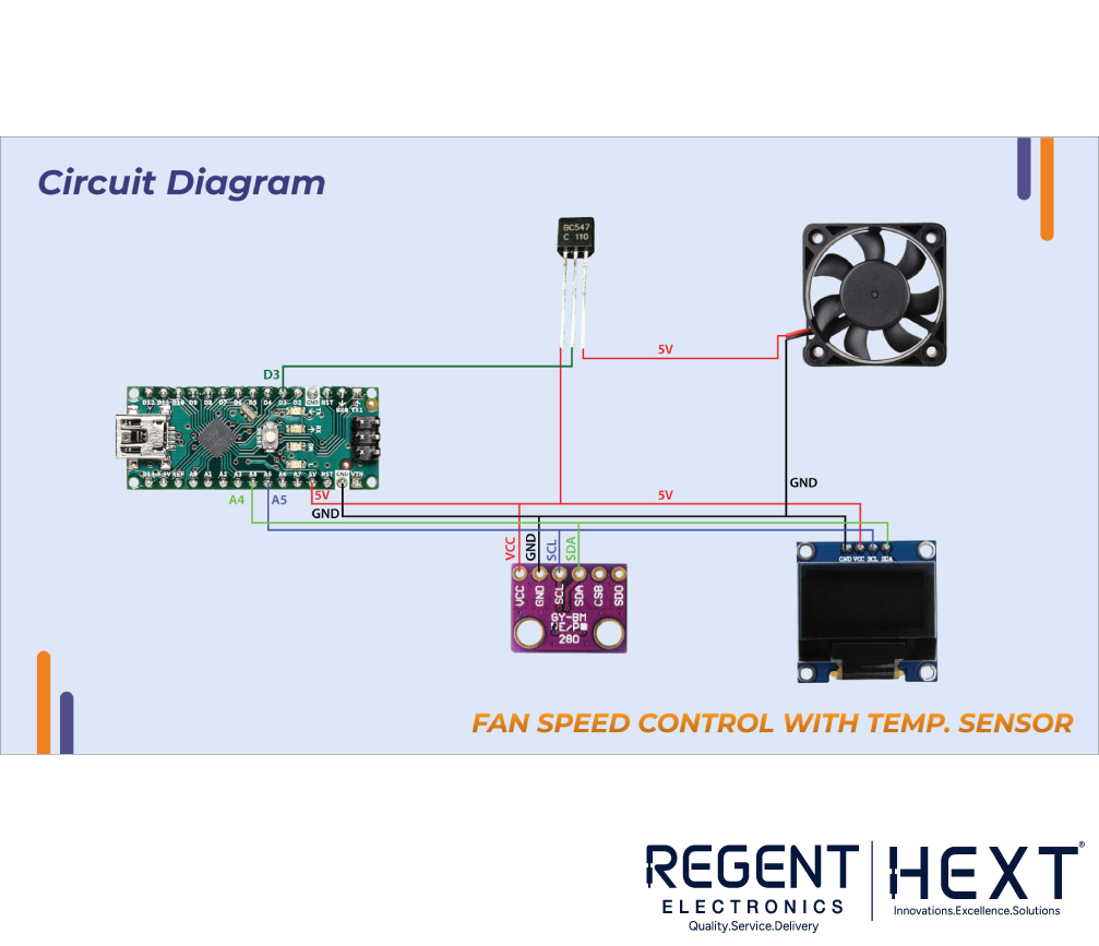
Circuit Connections:
| Component | Arduino Nano Pin |
| BME280 | |
| SDA | A4 |
| SCL | A5 |
| VCC | 5V |
| GND | GND |
| SSD1306 | |
| SDA | A4 |
| SCL | A5 |
| VCC | 5V |
| GND | GND |
Arduino Code Implementation
The following Arduino code reads temperature data from the BME280 sensor and adjusts fan speed accordingly:
#include <Wire.h>
#include <Adafruit_Sensor.h>
#include <Adafruit_BME280.h>
#include <Adafruit_GFX.h>
#include <Adafruit_SSD1306.h>
#include “fan_bitmap.h”
Adafruit_BME280 bme;
#define BME280_ADDRESS 0x76
#define OLED_RESET -1
#define SCREEN_ADDRESS 0x3C
Adafruit_SSD1306 display(128, 64, &Wire, OLED_RESET);
void setup() {
Serial.begin(9600);
pinMode(3, OUTPUT);
if (!bme.begin(BME280_ADDRESS)) {
Serial.println(“BME280 sensor not detected! Check wiring.”);
while (1);
}
if (!display.begin(SSD1306_SWITCHCAPVCC, SCREEN_ADDRESS)) {
Serial.println(“SSD1306 display initialization failed!”);
while (1);
}
display.display();
delay(2000);
display.clearDisplay();
}
void loop() {
float temperature = bme.readTemperature();
display.clearDisplay();
display.setTextSize(1);
display.setTextColor(WHITE);
display.setCursor(0, 0);
display.print(“Temp(C): “);
display.print(temperature);
if (temperature >= 30) {
analogWrite(3, map(temperature, 30, 50, 100, 255));
if (temperature >= 50)
analogWrite(3, 255);
} else {
analogWrite(3, 0);
}
display.display();
delay(500);
}
How the System Works
- The BME280 sensor continuously monitors the ambient temperature.
- The temperature data is displayed on the SSD1306 OLED screen.
- If the temperature exceeds 30°C, the fan starts spinning at the lowest speed.
- As the temperature increases, the fan speed increases proportionally.
- If the temperature reaches 50°C or higher, the fan runs at full speed.
- The OLED display also simulates fan rotation using bitmap images.
Conclusion
By successfully setting up this project, you have learned how to control fan speed based on temperature using an Arduino and a BME280 sensor. Additionally, you’ve gained experience interfacing multiple devices over the I2C communication protocol.
If you have any questions or face any difficulties, feel free to ask in the comments below. Stay tuned for more DIY electronics tutorials from Regent Electronics!