
Easy ESC Calibration with Arduino: A Step-by-Step Guide
When it comes to building your own RC projects, such as drones or other robotic creations, one of the most crucial components is the Electronic Speed Controller (ESC). Calibrating an ESC ensures it runs efficiently, and today, we’ll walk you through the process of calibrating your ESC using an Arduino Uno. By the end of this guide, your ESC will be ready for any RC project, from drones to other vehicles.
What Is an ESC?
An Electronic Speed Controller (ESC) is an essential part of an RC vehicle. It regulates the speed of a BLDC (Brushless DC) motor by generating Pulse Width Modulation (PWM) signals. These PWM signals control the voltage levels, allowing you to precisely control the speed and direction of the motor.
Why Calibrate an ESC?
Not all BLDC motors are created equal. Some may require more or less current to reach the same performance, especially when used in pairs or individually. Calibration ensures that the ESC can handle the minimum and maximum speeds of your motor, offering you better control and efficiency.
What Is PWM?
Pulse Width Modulation (PWM) is a method used to control the power supplied to electronic devices. By adjusting the width of the pulse in a signal, PWM can control the average power delivered to the load. ESCs use PWM signals to adjust the motor speed, providing smooth and efficient operation.
What Is a BLDC Motor?
A BLDC motor (Brushless DC Motor) operates without the need for brushes. It uses an array of coils within a fixed magnetic field. When current is passed through these coils, it generates magnetic fields that cause the coils to rotate. This design makes BLDC motors more efficient and durable than traditional brushed motors.
What Is an Arduino?
An Arduino is an open-source microcontroller platform. The Arduino Uno is based on the ATmega328P chip and offers a wide range of capabilities, including reading sensors, controlling motors, and sending/receiving signals. It’s widely used in hobby electronics and DIY projects due to its simplicity and versatility.
Hardware Requirements:
To follow along with this ESC calibration guide, you’ll need the following hardware components:
- Arduino Uno
- BLDC Motor
- ESC (Electronic Speed Controller)
- LiPo Battery
- Jumper Wires
- Power Supply (for Arduino)
Software Requirements:
- Arduino IDE (Integrated Development Environment)
Prerequisites:
- Download and install the Arduino IDE from the official website.
- Connect your Arduino Uno to your computer using a USB cable.
Circuit Diagram and Hardware Setup:
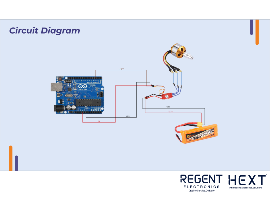
Here’s how to wire up the components:
- Arduino Uno: Use the PWM pin (Pin 3) for signal output.
- ESC: Connect the signal wire to Pin 3 on the Arduino, the power supply to the ESC, and connect the ground wire to the GND of Arduino.
Arduino Code for ESC Calibration:
cpp
CopyEdit
#include <Servo.h>
#define MIN_PULSE_LENGTH 1000 // Minimum pulse length in µs
#define MAX_PULSE_LENGTH 2000 // Maximum pulse length in µs
Servo motA;
char data;
void setup() {
Serial.begin(9600);
motA.attach(3, MIN_PULSE_LENGTH, MAX_PULSE_LENGTH);
displayInstructions();
}
void loop() {
if (Serial.available()) {
data = Serial.read();
switch (data) {
case 48:
Serial.println(“Sending minimum throttle”);
motA.writeMicroseconds(MIN_PULSE_LENGTH);
break;
case 49:
Serial.println(“Sending maximum throttle”);
motA.writeMicroseconds(MAX_PULSE_LENGTH);
break;
case 50:
Serial.print(“Running test in 3”);
delay(1000);
Serial.print(” 2″);
delay(1000);
Serial.println(” 1…”);
delay(1000);
test();
break;
}
}
}
void test() {
for (int i = MIN_PULSE_LENGTH; i <= MAX_PULSE_LENGTH; i += 5) {
Serial.print(“Pulse length = “);
Serial.println(i);
motA.writeMicroseconds(i);
delay(200);
}
Serial.println(“STOP”);
motA.writeMicroseconds(MIN_PULSE_LENGTH);
}
void displayInstructions() {
Serial.println(“READY – PLEASE SEND INSTRUCTIONS AS FOLLOWING :”);
Serial.println(“\t0 : Send min throttle”);
Serial.println(“\t1 : Send max throttle”);
Serial.println(“\t2 : Run test function\n”);
}
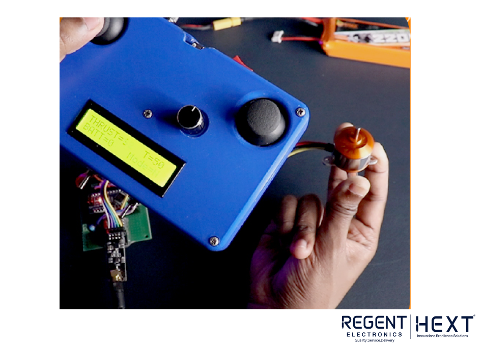
How It Works:
Once the ESC is powered on, it enters programming mode as soon as it detects a voltage on the signal line. It records the highest signal as the maximum throttle and the lowest signal as the cutoff (stop) position.
The calibration process is straightforward:
- The ESC beeps a few times to indicate the number of batteries in series in the battery pack.
- Once you disconnect the battery and set the signal to the low/cutoff position, reconnect the battery. The ESC will beep again, confirming it’s ready for use.
- Gradually increasing the throttle will cause the motor to spin faster as the signal rises.
Conclusion:
If everything has been set up correctly and your motor is responding as expected, congratulations! You’ve successfully calibrated your ESC using an Arduino. Whether you’re building a drone or any other RC project, your ESC is now ready for action.
Note: Always ensure that your ESC has a higher rating than your motor, and calibrate it to 80% of its maximum capacity. This precaution allows room for adjustments and prevents motor overload, ensuring smoother and more stable operation.
By following these simple steps, you can calibrate your ESC using Arduino and be on your way to building the perfect RC project.