
How to Build a Line Follower and Bluetooth-Controlled Robot Using Arduino
In today’s rapidly evolving world of automation, robotics has become a powerful tool for simplifying tasks, reducing errors, and improving productivity. Among the popular types of robots are line follower robots and Bluetooth-controlled robots, both of which offer hands-on insight into sensors, motor drivers, and wireless communication.
In this tutorial, brought to you by Regent Electronics, we’ll guide you through building two exciting Arduino-based robots: a Line Follower Robot and a Bluetooth Controlled Robot.
What is a Line Follower Robot?
A line follower robot is an autonomous machine designed to follow a visible line on the floor, typically black tape on a white surface. These robots use infrared (IR) sensors to detect the path and make directional decisions in real-time. They are widely used in automation industries for transporting goods without human intervention.
The robot uses IR sensors mounted underneath the chassis to detect the line. When the IR light reflects off a white surface, the sensor receives it, but it doesn’t reflect from the black tape—this difference is used to control movement.
What is a Bluetooth Controlled Robot?
A Bluetooth controlled robot is a remote-controlled bot that receives commands from a smartphone via a Bluetooth module, such as the popular HC-05. Using simple apps available on Android, you can direct the robot to move forward, backward, left, or right.
If you’re new to the HC-05 Bluetooth module, Regent Electronics also provides a dedicated tutorial for interfacing HC-05 with Arduino.
Components Required
To build these two types of robots, you’ll need the following components:
- Arduino Uno or Nano
- Motor Driver Module (L298N)
- HC-05 Bluetooth Module
- IR Line Sensors (2 or more)
- Robot Chassis
- DC Motors with Wheels
- Battery Pack (7.4V or 9V recommended)
- Jumper Wires
Line Follower Robot – Circuit Diagram & Working
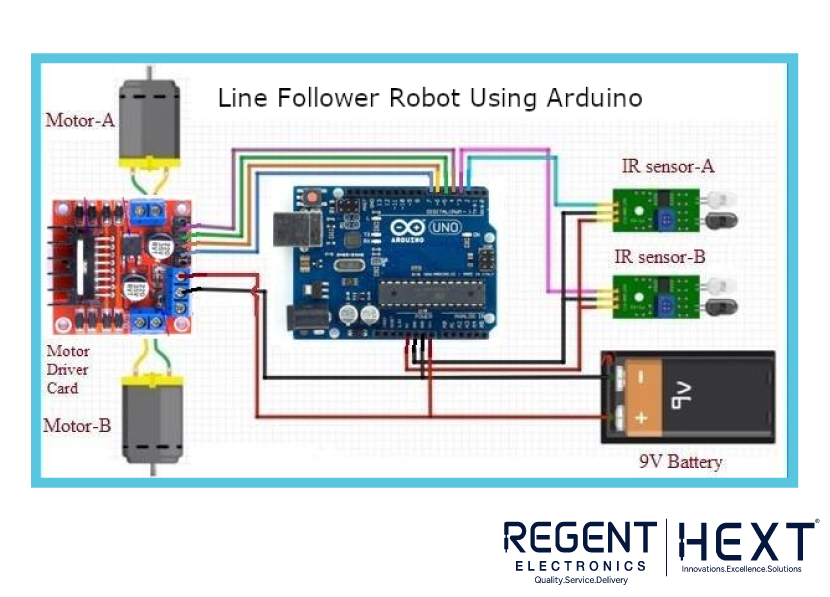
IR Sensor Working:
Each IR sensor contains an emitter and a detector. When IR light hits a black surface (tape), it’s absorbed. On a white or reflective surface, it bounces back and gets detected. Based on this feedback, the Arduino makes decisions on which motor to activate.
Why Use a Motor Driver?
DC motors require more current than what an Arduino pin can supply. The L298N motor driver acts as a bridge between Arduino and motors, enabling direction and speed control without damaging the board.
Line Follower Robot – Arduino Code
Here’s the decision logic used in the robot:
cpp
CopyEdit
int LineSensor1 = 2;
int LineSensor2 = 3;
int LeftMotor1 = 4;
int LeftMotor2 = 5;
int RightMotor1 = 6;
int RightMotor2 = 7;
void setup() {
pinMode(LineSensor1, INPUT);
pinMode(LineSensor2, INPUT);
pinMode(LeftMotor1, OUTPUT);
pinMode(LeftMotor2, OUTPUT);
pinMode(RightMotor1, OUTPUT);
pinMode(RightMotor2, OUTPUT);
}
void loop() {
int leftValue = digitalRead(LineSensor1);
int rightValue = digitalRead(LineSensor2);
if (leftValue == LOW && rightValue == LOW) {
// Move Forward
digitalWrite(LeftMotor1, HIGH);
digitalWrite(LeftMotor2, LOW);
digitalWrite(RightMotor1, HIGH);
digitalWrite(RightMotor2, LOW);
}
else if (leftValue == LOW && rightValue == HIGH) {
// Turn Left
digitalWrite(LeftMotor1, HIGH);
digitalWrite(LeftMotor2, LOW);
digitalWrite(RightMotor1, LOW);
digitalWrite(RightMotor2, LOW);
}
else if (leftValue == HIGH && rightValue == LOW) {
// Turn Right
digitalWrite(LeftMotor1, LOW);
digitalWrite(LeftMotor2, LOW);
digitalWrite(RightMotor1, HIGH);
digitalWrite(RightMotor2, LOW);
}
else {
// Stop
digitalWrite(LeftMotor1, LOW);
digitalWrite(LeftMotor2, LOW);
digitalWrite(RightMotor1, LOW);
digitalWrite(RightMotor2, LOW);
}
}
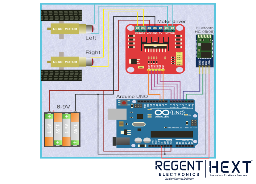
Bluetooth Controlled Robot – Circuit & Setup
Connection:
Connect the HC-05 Bluetooth module to Arduino using SoftwareSerial on pins 2 (RX) and 3 (TX). Once paired with your phone, commands like “forward”, “left”, “stop” are sent to Arduino.
Install a Bluetooth terminal/controller app from the Play Store to control the bot.
Bluetooth Controlled Robot – Arduino Code
cpp
CopyEdit
#include <SoftwareSerial.h>
#define IN1 4
#define IN2 5
#define IN3 6
#define IN4 7
#define EN1 9
#define EN2 10
SoftwareSerial mySerial(2, 3); // RX, TX
String data;
void setup() {
pinMode(IN1, OUTPUT); pinMode(IN2, OUTPUT);
pinMode(IN3, OUTPUT); pinMode(IN4, OUTPUT);
pinMode(EN1, OUTPUT); pinMode(EN2, OUTPUT);
digitalWrite(EN1, HIGH);
digitalWrite(EN2, HIGH);
mySerial.begin(9600);
}
void loop() {
if (mySerial.available()) {
data = mySerial.readStringUntil(‘\n’);
int command = data.toInt();
switch (command) {
case 1: forward(); break;
case 2: reverse(); break;
case 3: left(); break;
case 4: right(); break;
case 5: stopRobot(); break;
}
}
}
void forward() {
digitalWrite(IN1, HIGH); digitalWrite(IN2, LOW);
digitalWrite(IN3, HIGH); digitalWrite(IN4, LOW);
}
void reverse() {
digitalWrite(IN1, LOW); digitalWrite(IN2, HIGH);
digitalWrite(IN3, LOW); digitalWrite(IN4, HIGH);
}
void left() {
digitalWrite(IN1, LOW); digitalWrite(IN2, LOW);
digitalWrite(IN3, HIGH); digitalWrite(IN4, LOW);
}
void right() {
digitalWrite(IN1, HIGH); digitalWrite(IN2, LOW);
digitalWrite(IN3, LOW); digitalWrite(IN4, LOW);
}
void stopRobot() {
digitalWrite(IN1, LOW); digitalWrite(IN2, LOW);
digitalWrite(IN3, LOW); digitalWrite(IN4, LOW);
}
Conclusion
In this project, you’ve learned how to create two exciting types of robots using Arduino – a line follower robot and a Bluetooth-controlled robot. These beginner-friendly robots are perfect for learning the basics of embedded systems, motor control, and wireless communication.
If you have any questions, feel free to ask in the comments below. For more DIY robotics and electronics tutorials, stay tuned with Regent Electronics.