

Regent Electronics Arduino Pro Mini Starter Kit Guide
Introduction to the Arduino Pro Mini Starter Kit
Welcome to Regent Electronics! In this blog, we’ll dive into the Arduino Pro Mini Starter Kit, exploring how to get started with the Arduino Pro Mini, and how to connect components like LEDs, LDRs (Light Dependent Resistors), switches, and more. This guide will help you understand the essentials of the kit and how to bring your projects to life.
What is the Arduino Pro Mini?
The Arduino Pro Mini is a compact, cost-effective microcontroller board ideal for small projects. One thing to note is that the Pro Mini does not come with an onboard USB to TTL converter, which is required for programming the board. However, the Arduino Pro Mini Starter Kit from Regent Electronics includes this USB to TTL converter, so you don’t have to worry about purchasing it separately.
In the next section, we’ll guide you through uploading your first program to the Arduino Pro Mini.
How to Connect the USB-TTL Converter to the Arduino Pro Mini

To upload code to the Arduino Pro Mini, you need a USB to TTL converter, as the board doesn’t have an onboard USB connection. Below, you’ll find an image showing the wiring of the USB-TTL converter to the Arduino Pro Mini.
Once the converter is connected, you can upload code directly to your Arduino board using the included components in the kit.
Uploading the Blink Code to the Arduino Pro Mini
Let’s get started by uploading the blink code to your Arduino Pro Mini. This code will make the onboard LED blink on and off, allowing you to test that everything is set up correctly.
For the Arduino Pro Mini, the onboard LED is connected to PIN 13. With the help of the Arduino IDE, we can upload a simple code that toggles this LED.
- Open the Arduino IDE.
- Write the following code:
cpp
CopyEdit
#define LED_PIN 13
void setup() {
pinMode(LED_PIN, OUTPUT); // Set the LED pin as an output
}
void loop() {
digitalWrite(LED_PIN, HIGH); // Turn the LED on
delay(1000); // Wait for one second
digitalWrite(LED_PIN, LOW); // Turn the LED off
delay(1000); // Wait for another second
}
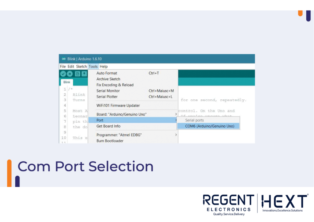
- Select the Arduino Pro Mini board in the Tools menu.
- Choose the appropriate COM port.
- Press CTRL + U to upload the code to the board.
Once the upload is complete, your onboard LED should begin blinking! If it doesn’t, double-check your wiring and try again.
Understanding the LDR (Light Dependent Resistor)
An LDR is a type of resistor that changes its resistance based on the intensity of light. The more light it detects, the lower its resistance. LDRs are commonly used in applications like street lights, solar panels, and light-following robots.
Applications of LDR Sensors:
- Solar Panel Tracking: LDRs can be used to monitor sunlight and adjust the orientation of solar panels for optimal energy production.
- Light-Following Robots: These robots use LDRs to detect light sources and follow them.
- Automatic Street Lights: LDRs can trigger the operation of street lights depending on ambient light levels.
Interfacing the LDR with the Arduino Pro Mini
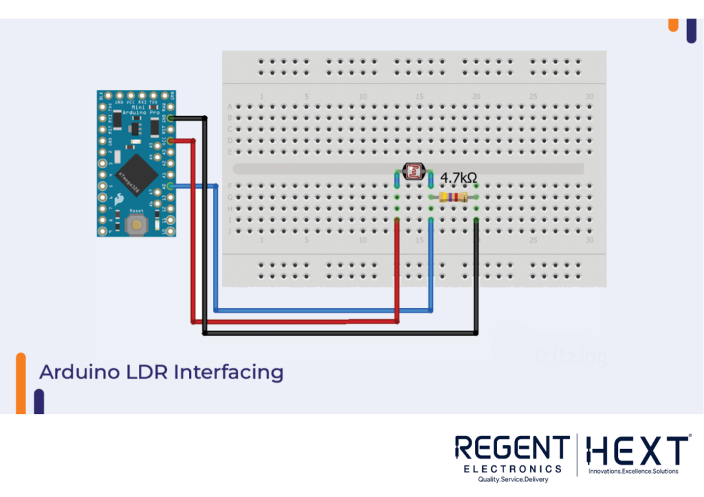
Connecting an LDR to your Arduino Pro Mini is simple. Use the following wiring diagram to make the connections:

- Connect the LDR to Analog Pin A0 on the Arduino.
- The other leg of the LDR goes to 5V.
Here’s an example of the code to read values from the LDR:
cpp
CopyEdit
int ldr = A0; // Connect the LDR to analog pin A0
int value = 0; // Variable to store LDR reading
void setup() {
Serial.begin(9600); // Initialize serial communication
}
void loop() {
value = analogRead(ldr); // Read the value from the LDR
Serial.print(“LDR value: “); // Display the LDR value
Serial.println(value);
delay(1000); // Wait for a second before reading again
}
Exploring Switches and Their Applications

In this section, we’ll look at switches and how to interface them with your Arduino Pro Mini.
Types of Switches:
- Push-Pull Switches: These switches function by compressing a spring when pressed, locking the switch in place. Pressing again unlocks the switch.
- Rocker Switches: Common in household appliances, these switches toggle between two states when pressed.
The push-pull switch included in the kit is simple to use. You can interface it with your Arduino easily by following these steps:
- Connect the switch’s VCC pin to 5V on the Arduino.
- Connect the GND pin to Pin 8.
Here’s an example code to read the state of the switch:
cpp
CopyEdit
const int buttonPin = 7; // The pushbutton is connected to pin 7
const int ledPin = 4; // LED connected to pin 4
int buttonState = 0; // Variable to store the button state
void setup() {
pinMode(ledPin, OUTPUT); // Initialize the LED pin as an output
pinMode(buttonPin, INPUT); // Initialize the pushbutton pin as an input
}
void loop() {
buttonState = digitalRead(buttonPin); // Read the pushbutton state
if (buttonState == HIGH) { // If the button is pressed
digitalWrite(ledPin, HIGH); // Turn the LED on
} else {
digitalWrite(ledPin, LOW); // Turn the LED off
}
}

Conclusion:
The Arduino Pro Mini Starter Kit from Regent Electronics offers a great introduction to microcontroller-based projects. With components like the Arduino Pro Mini, LDR, LED, and switch, you can start building a wide range of interactive projects.
Feel free to ask any questions in the comments section below, and happy tinkering!