

Orange ESP-32 Cam IoT Kit: Your Gateway to Wi-Fi & Bluetooth Projects
Welcome back to our blog! In this post, we will explore the Orange ESP32 Cam IoT Kit offered by Regent Electronics. This kit is perfect for those interested in building Wi-Fi/Bluetooth projects that involve remote image access.
Overview of the ESP32-CAM Development Board
The ESP32-CAM is a powerful development board that combines the capabilities of the ESP32-S processor, an OV2640 camera, GPIOs for connecting peripherals, and a microSD card slot for image storage. With built-in Wi-Fi and Bluetooth, the ESP32-CAM is rapidly gaining popularity in applications such as image broadcasting, facial recognition, and image processing.
The Orange ESP32-CAM Starter Kit contains everything you need to get started with the ESP32 development board, making it ideal for various IoT projects.
Connecting the FTDI Module to the ESP32-CAM
To program the ESP32-CAM, you will need an FTDI module. Here’s how to connect it:
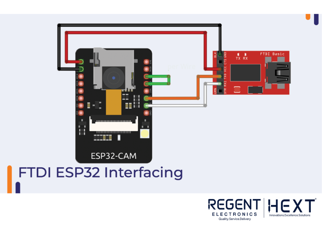
- Ensure the FTDI module is set to a 3.3V VCC output (not 5V) because the ESP32-CAM operates at 3.3V.
- Connect GPIO 0 to GND to prepare the board for programming.
- Link the FTDI TX pin to the ESP32-CAM RX pin and FTDI RX pin to the ESP32-CAM TX pin.
After programming, remember to disconnect the jumper wire connecting GPIO 0 to GND.
Installing the ESP32-CAM Board on Arduino IDE
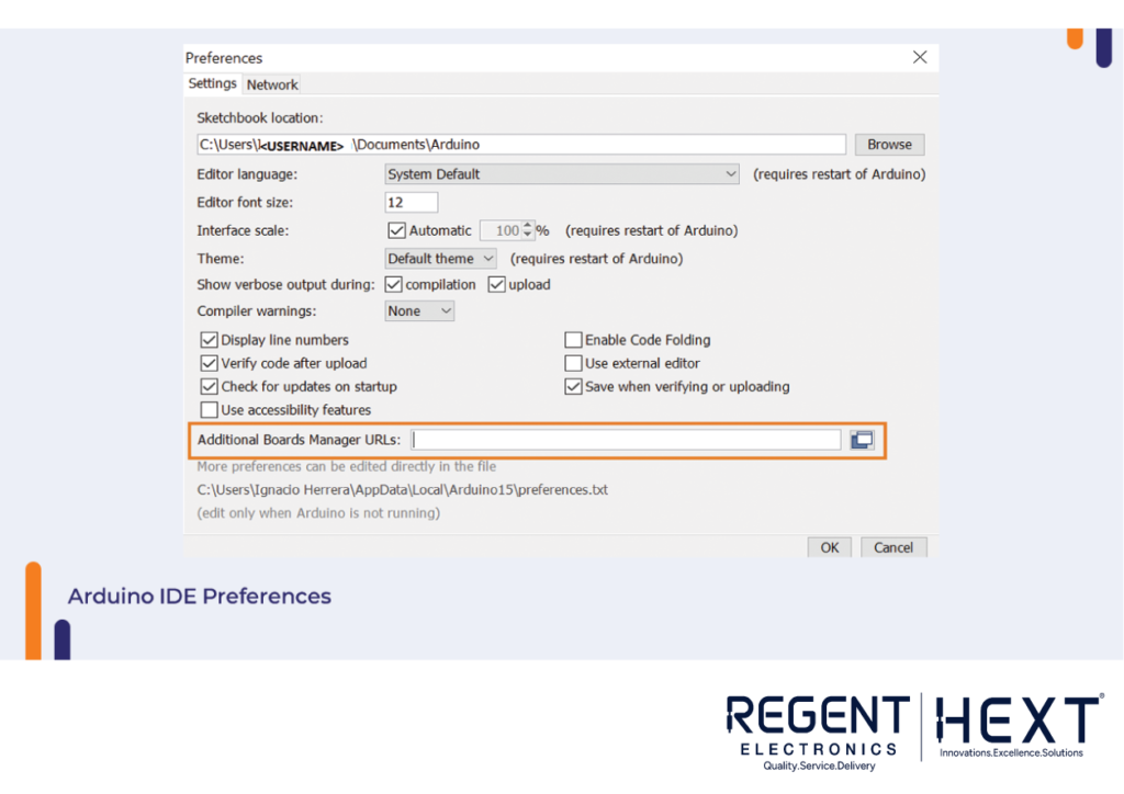
To get started with programming the ESP32-CAM using the Arduino IDE, follow these steps:
- Install the Latest Arduino IDE: Make sure you have the latest version of the Arduino IDE installed on your computer.
- Add the ESP32 Board: Go to File > Preferences in the IDE and paste https://dl.espressif.com/dl/package_esp32_index.json in the “Additional Boards Manager URLs” field.
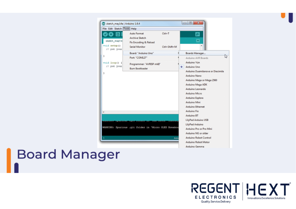
- Install ESP32: Go to Tools > Board > Boards Manager, search for ESP32 and click Install.
- Select the ESP32 Board: In the Tools > Board menu, choose the AI-Thinker ESP32-CAM board.
Setting Up the Arduino IDE for Programming
To upload code to the ESP32-CAM, follow these steps:
- Go to Tools > Board and select AI-Thinker ESP32-CAM.
- Go to Tools > Port and select the correct COM port.
- Copy and paste the desired code into the Arduino IDE editor and hit Upload.
- Once uploading is complete, you can disconnect the board and remove the jumper wire from GPIO 0.
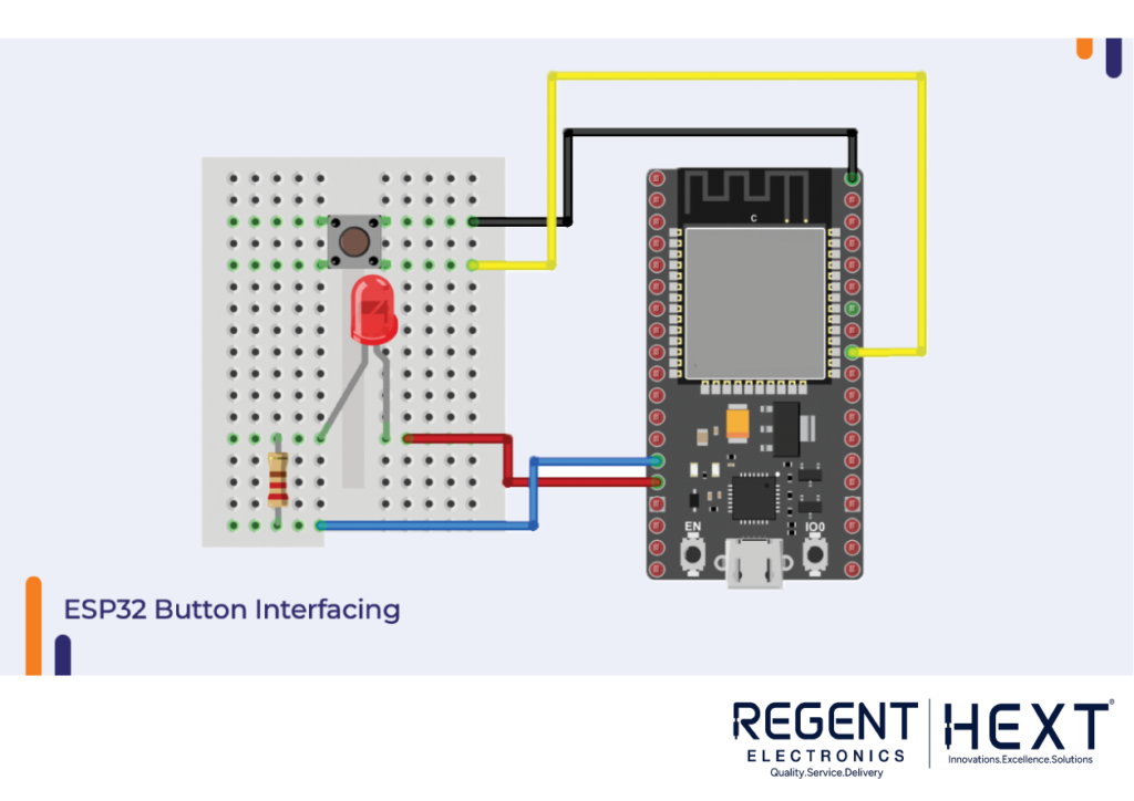
Interfacing an LED with the ESP32-CAM
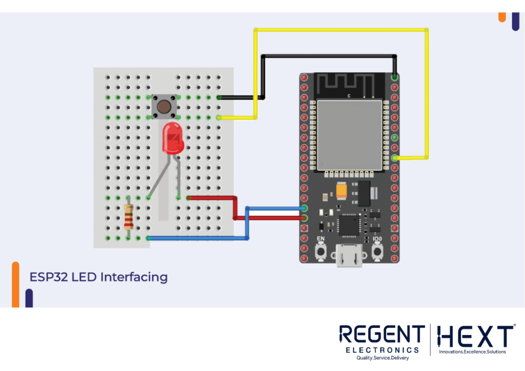
In this section, we’ll discuss how to interface an LED with the ESP32-CAM. Since the ESP32 outputs 5V on its GPIO pins and the LED operates at 3.3V, we need to use a resistor to prevent damage to the LED. A 320-ohm resistor connected in series with the LED’s anode will limit the current flow.
Controlling the LED with the ESP32-CAM
Here’s a sample code to control the LED:
cpp
CopyEdit
#define BUTTON_PIN 16 // ESP32 GIOP16 pin connected to button’s pin
#define BUZZER_PIN 21 // ESP32 GIOP21 pin connected to Buzzer’s pin
void setup() {
Serial.begin(9600);
pinMode(BUTTON_PIN, INPUT_PULLUP); // Set ESP32 pin to input pull-up mode
pinMode(BUZZER_PIN, OUTPUT); // Set ESP32 pin to output mode
}
void loop() {
int buttonState = digitalRead(BUTTON_PIN); // Read new state
if (buttonState == LOW) {
Serial.println(“The button is being pressed”);
digitalWrite(BUZZER_PIN, HIGH); // Turn on
} else {
Serial.println(“The button is unpressed”);
digitalWrite(BUZZER_PIN, LOW); // Turn off
}
}
Interfacing a Switch with the ESP32-CAM
A switch can be used to connect two separate pins. The Rocker Switch is a common choice due to its long lifespan and minimal arcing during switching.
To interface a switch with the ESP32-CAM, connect one end of the switch to GND and the other end to a GPIO pin.
Controlling the Switch with the ESP32-CAM
Here’s a simple code snippet to control the switch:
cpp
CopyEdit
#define BUTTON_PIN 16 // ESP32 GIOP16 pin connected to button’s pin
void setup() {
Serial.begin(9600);
pinMode(BUTTON_PIN, INPUT_PULLUP); // Set ESP32 pin to input pull-up mode
pinMode(BUZZER_PIN, OUTPUT); // Set ESP32 pin to output mode
}
void loop() {
int buttonState = digitalRead(BUTTON_PIN); // Read new state
if (buttonState == LOW) {
Serial.println(“The button is being pressed”);
digitalWrite(BUZZER_PIN, HIGH); // Turn on
} else {
Serial.println(“The button is unpressed”);
digitalWrite(BUZZER_PIN, LOW); // Turn off
}
}
Interfacing a Buzzer with the ESP32-CAM
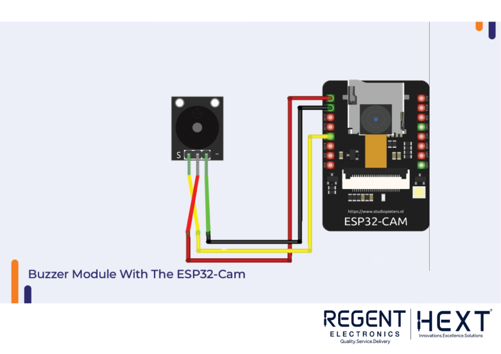
Buzzers are often used as indicators in electronic systems. When voltage is applied, a piezo crystal inside the buzzer vibrates, producing sound. You can connect the VCC pin of the buzzer directly to the GPIO pin of the ESP32-CAM and the GND pin to GND.
Buzzer Module Code for the ESP32-CAM
Use the following code to control the buzzer:
cpp
CopyEdit
#define BUZZER_PIN 15 // ESP32 GIOP15 pin connected to Buzzer’s pin
void setup() {
pinMode(BUZZER_PIN, OUTPUT); // Set ESP32 pin to output mode
}
void loop() {
digitalWrite(BUZZER_PIN, HIGH); // Turn on
delay(1000);
digitalWrite(BUZZER_PIN, LOW); // Turn off
delay(1000);
}
Interfacing a PIR Sensor with the ESP32-CAM
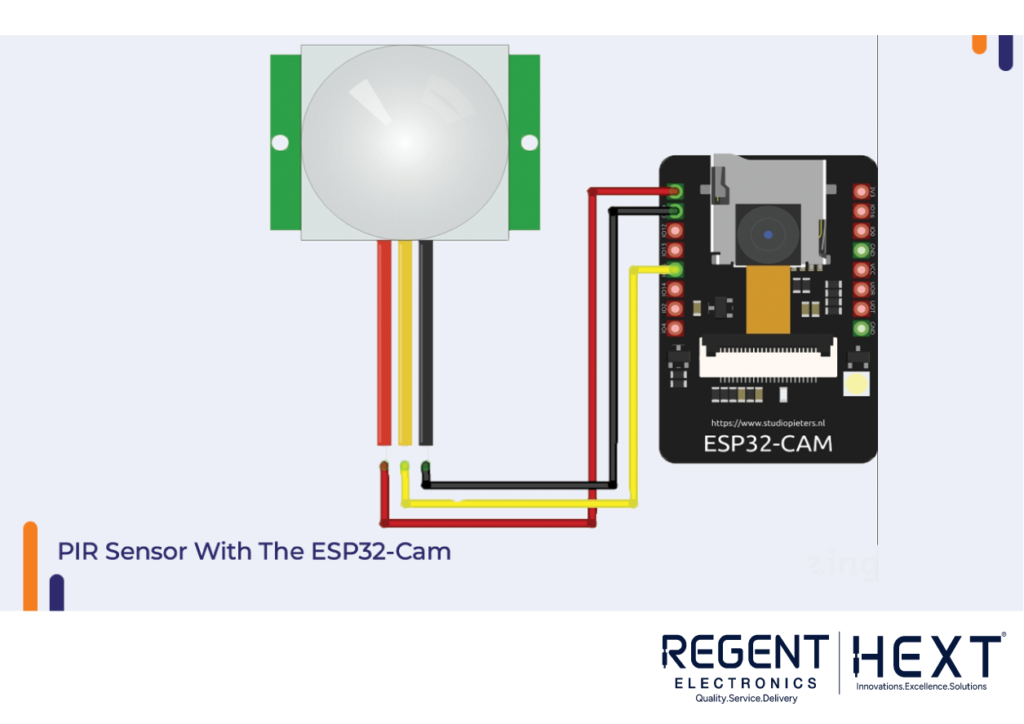
A PIR (Passive Infrared) sensor detects motion by measuring infrared radiation. When a moving object enters its detection range, the sensor sends a signal to the microcontroller. To interface a PIR sensor with the ESP32-CAM, connect the output pin to a GPIO pin and the VCC and GND pins to the power supply.
PIR Sensor Code for ESP32-CAM
Use the following code to work with the PIR sensor:
cpp
CopyEdit
#define timeSeconds 10
const int motionSensor = 15;
unsigned long now = millis();
unsigned long lastTrigger = 0;
boolean startTimer = false;
void IRAM_ATTR detectsMovement() {
Serial.println(“MOTION DETECTED!!!”);
startTimer = true;
lastTrigger = millis();
}
void setup() {
Serial.begin(115200);
pinMode(motionSensor, INPUT_PULLUP);
attachInterrupt(digitalPinToInterrupt(motionSensor), detectsMovement, RISING);
}
void loop() {
now = millis();
if (startTimer && (now – lastTrigger > (timeSeconds * 1000))) {
Serial.println(“Motion stopped…”);
startTimer = false;
}
}
Conclusion
In this blog, we covered the basics of working with the Orange ESP32-CAM IoT Starter Kit and interfacing various components, including LEDs, switches, buzzers, and PIR sensors. If you have any questions or need further assistance, feel free to reach out in the comments section.
Regent Electronics is here to help you explore the exciting world of IoT and embedded systems! Stay tuned for more tutorials and product updates.