

Programming ESP Boards with Arduino IDE Made Easy – Beginner’s Guide
Introduction
ESP modules are widely used in IoT projects due to their affordability and functionality. Various ESP modules are available, including ESP-01, ESP-12E, ESP-12F, NodeMCU, and ESP-32. If you are new to ESP programming, the first step is to configure the module with an Integrated Development Environment (IDE) and upload a basic code to test its functionality. In this guide, we will show you how to set up ESP-01, NodeMCU, and ESP-32 with Arduino IDE and run basic testing codes.
Components Required
- ESP-01
- NodeMCU
- ESP-32
- CP2102 USB to UART Bridge
- Push Button
- Jumper Wires (F to F) – 10 pieces of different colors
All ESP boards utilize the CP2102 UART bridge to communicate with a computer. While NodeMCU and ESP-32 have built-in CP2102, an external CP2102 module is required for ESP-01.
To ensure proper detection of CP2102 by the computer’s COM port, you must install the CP210x driver. You can download it from the official source.
Circuit Connection for ESP-01
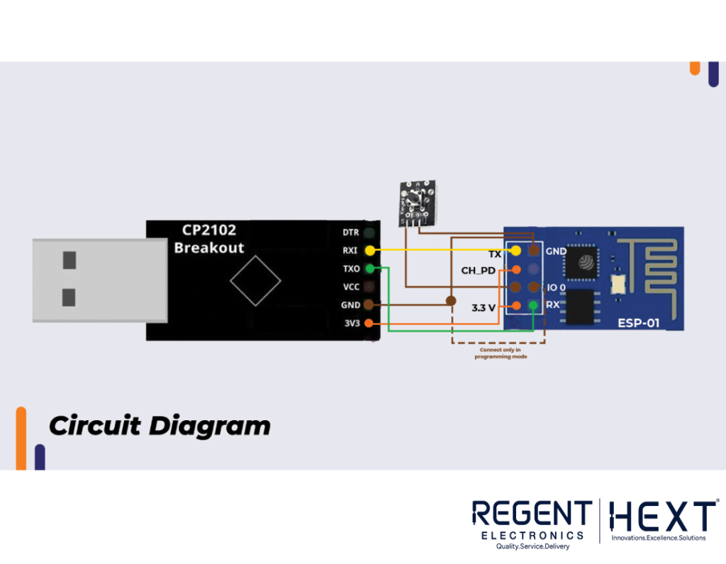
For ESP-01, make the following connections:
- Connect RXD of ESP-01 to TXD of CP2102
- Connect TXD of ESP-01 to RXD of CP2102
- Provide 3.3V from CP2102 to CH_PD (Chip Enable) and VCC pin of ESP-01
- Connect GND from CP2102 to GPIO-0, GND, and RST pins of ESP-01
- Use a push button switch between Reset and GND
Setting Up Arduino IDE for ESP Boards
Steps to Install Arduino IDE

- Download and install Arduino IDE from the official website based on your operating system.
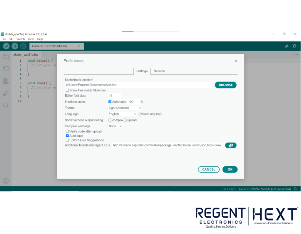
- Open Arduino IDE and navigate to File > Preferences.
- In the “Additional Boards Manager URLs” field, enter the following URLs:
- http://arduino.esp8266.com/stable/package_esp8266com_index.json,
- https://raw.githubusercontent.com/espressif/arduino-esp32/gh-pages/package_esp32_index.json
- Click OK.
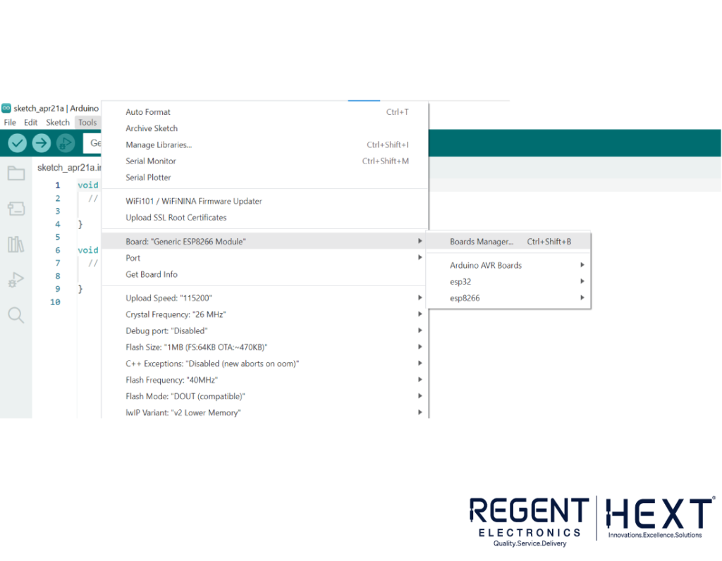
- Go to Tools > Board > Board Manager.
- Search for esp8266 and install ESP8266 by ESP8266 Community.
- Search for esp32 and install ESP32 by Espressif Systems.
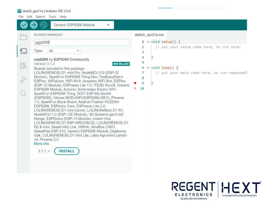
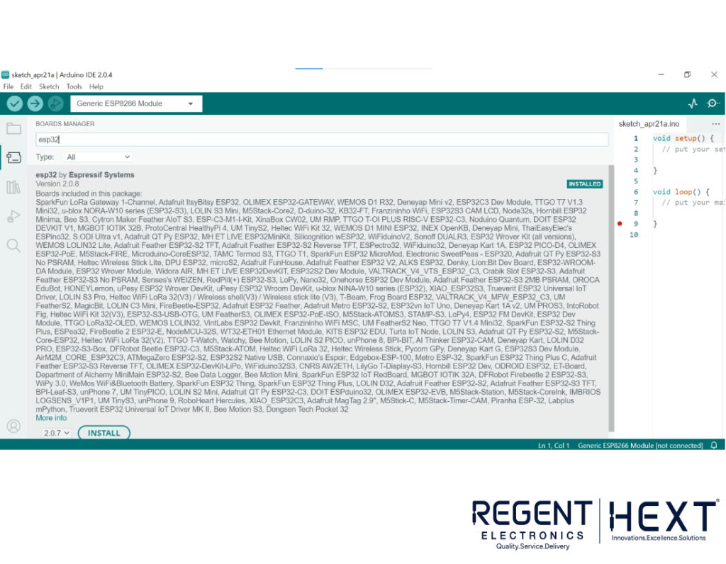
Now, your ESP boards are successfully added to Arduino IDE.
Blinking LED Test for ESP-01 and NodeMCU
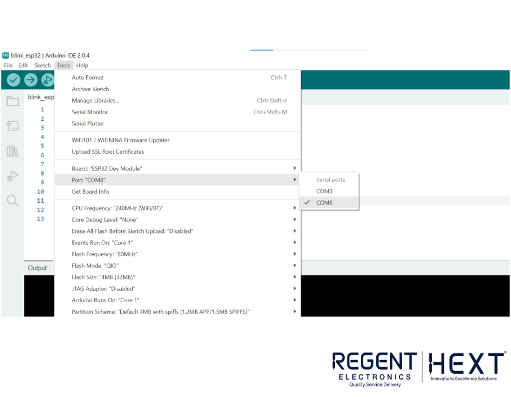
The onboard LED pin of ESP-01 is GPIO 1, and for NodeMCU, it is GPIO 2. Before uploading the blinking code, select the correct board and COM port.
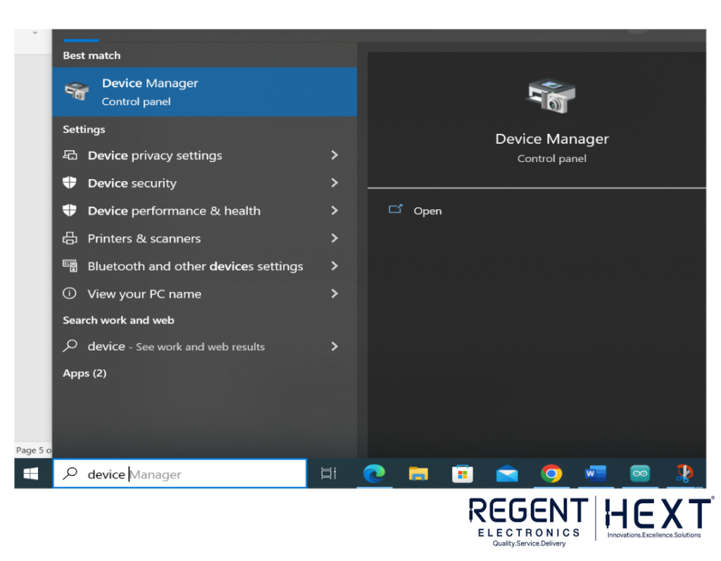
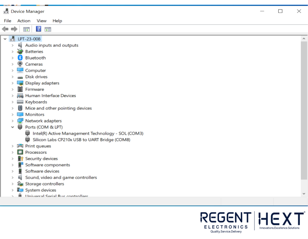
Finding the COM Port

- Open Device Manager on Windows.
- Expand “Ports (COM & LPT)” and check the COM port number for CP2102.
- In Arduino IDE, go to Tools > Port and select the detected COM port.
Blinking LED Code
int led = 1; // Use pin 1 for ESP-01 and pin 2 for NodeMCU
void setup() {
pinMode(led, OUTPUT);
}
void loop() {
digitalWrite(led, HIGH);
delay(500);
digitalWrite(led, LOW);
delay(500);
}
After uploading the code, disconnect the GND from GPIO-0 and press the reset button. The onboard LED should start blinking, indicating the board is functioning correctly.
WiFi Connectivity Test
To verify WiFi functionality, use the following code and replace Your_WiFi_SSID and Your_WiFi_Password with your credentials.
#include <ESP8266WiFi.h> // For ESP-32, use <WiFi.h>
const char* ssid = “Your_WiFi_SSID”;
const char* password = “Your_WiFi_Password”;
int iled = 1; // Change to 2 for NodeMCU
void setup() {
Serial.begin(115200);
pinMode(iled, OUTPUT);
WiFi.begin(ssid, password);
Serial.println(“Connecting…”);
while (WiFi.status() != WL_CONNECTED) {
digitalWrite(iled, HIGH);
delay(500);
Serial.print(“.”);
}
Serial.println(“\nConnected to WiFi”);
Serial.print(“IP Address: “);
Serial.println(WiFi.localIP());
}
void loop() {
if (WiFi.status() == WL_CONNECTED) {
digitalWrite(iled, HIGH);
delay(500);
digitalWrite(iled, LOW);
delay(500);
} else {
Serial.println(“WiFi Disconnected”);
digitalWrite(iled, HIGH);
delay(500);
}
}
If the onboard LED blinks, the module has successfully connected to WiFi.
Testing NodeMCU
For NodeMCU, simply connect it using a micro USB cable. Since it has a built-in reset button and CP2102 module, there is no need for external components.
- Select Generic ESP8266 Module in Arduino IDE.
- Choose the correct COM port.
- Upload the LED blinking code (change the LED pin from 1 to 2).
- The LED should start blinking if the board is functional.
WiFi Test for NodeMCU
Upload the same WiFi test code as ESP-01, but change the onboard LED pin from 1 to 2.
Testing ESP-32
ESP-32 does not have an onboard LED, so we will test it using WiFi connectivity.
- Modify the library from #include <ESP8266WiFi.h> to #include <WiFi.h>.
- Select ESP-32 Dev Module in Arduino IDE.
- Choose the correct COM port.
- Upload the WiFi test code and open the Serial Monitor.
- If the WiFi is turned on, you should see a “Connected” message along with the IP address, confirming that the ESP-32 is functional.
Conclusion
In this guide, we successfully configured ESP boards with Arduino IDE, ran basic LED blinking tests, and verified WiFi connectivity. If you have any questions, feel free to comment, and our team at Regent Electronics will assist you.
For more exciting projects, check out our YouTube channel!