

How to Build Your Own IoT Water Level Indicator Using NodeMCU and HC-SR04
Water management is a critical task in many industries and households. Monitoring the water level in tanks is a necessary process, ensuring that they don’t overflow or run dry. Traditionally, water tanks are manually monitored, which can be inefficient and prone to errors. However, with the integration of the Internet of Things (IoT), you can remotely monitor the water level using a smartphone or PC. In this tutorial, we’ll show you how to create your own IoT water level indicator using NodeMCU and the HC-SR04 ultrasonic sensor.
This IoT water level indicator allows you to view the water level from anywhere using the Blynk platform, offering a convenient solution for automated water management. The ultrasonic sensor is non-contact, making it suitable for measuring the level of any fluid, including water, oil, chemicals, and beverages.
Components Required for IoT Water Level Indicator
- ESP8266 NodeMCU
- HC-SR04 Ultrasonic Sensor
- Jumper Wires (4 pieces)
- Breadboard (optional)
Circuit Diagram
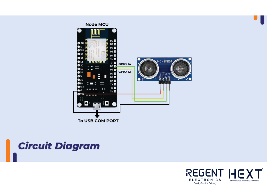
The HC-SR04 Ultrasonic Sensor connects to the NodeMCU as follows:
- Trig Pin (Trigger) is connected to D6 (GPIO12).
- Echo Pin (Echo) is connected to D5 (GPIO14).
- VCC connects to 5V, and GND connects to GND.
- The Vin Pin from NodeMCU provides 5V to power the HC-SR04 through the USB port.
Understanding the HC-SR04 Ultrasonic Sensor
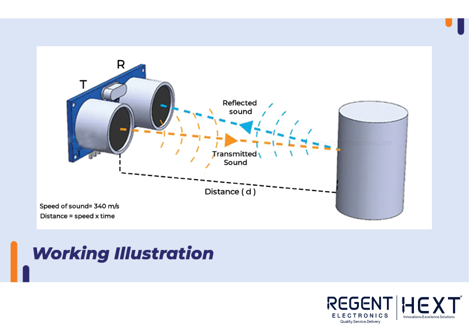
The HC-SR04 ultrasonic sensor is popular for distance measurements. It has four pins: GND, Echo, Trig, and VCC. Here’s how it works:
- The Trig Pin sends a pulse of 10 microseconds to trigger the sensor.
- The Echo Pin receives the pulse after it has bounced off an object.
- The time it takes for the pulse to travel to the object and return is measured to calculate the distance.
The formula for calculating distance is:
Distance = (Speed of Sound × Time) / 2
Since the signal travels to the object and returns, we divide by 2 to account for the round-trip.
Introduction to Blynk Platform
Blynk is a cloud-based platform for IoT projects. It allows users to build mobile apps for Android and iOS to control and monitor IoT devices. Blynk also offers a Web Dashboard for easy monitoring from a PC.
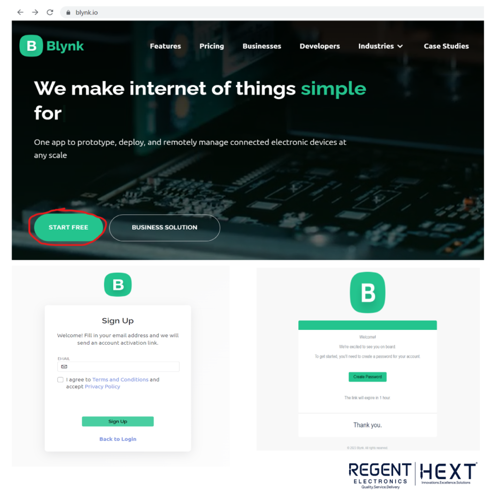
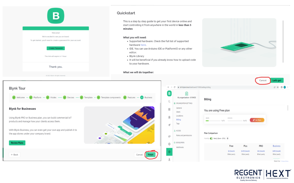
Steps to Create a Blynk Account and Setup
- Visit the Blynk website and click “Start Free” to create an account.
- Enter your email, set a password, and verify your account through the email sent by Blynk.
- After logging in, create a new template for your device (choose NodeMCU as the hardware).
Creating a Datastream in Blynk
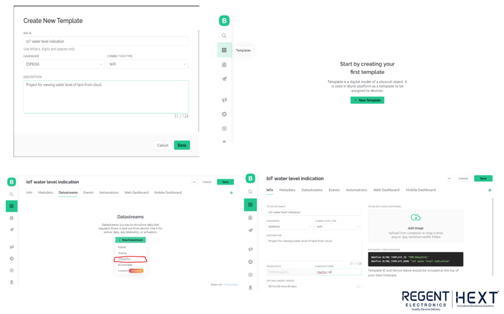
A datastream is where data is stored on the Blynk cloud, which is used for monitoring purposes. In this case, the water level is sent via virtual pins in the Blynk app.
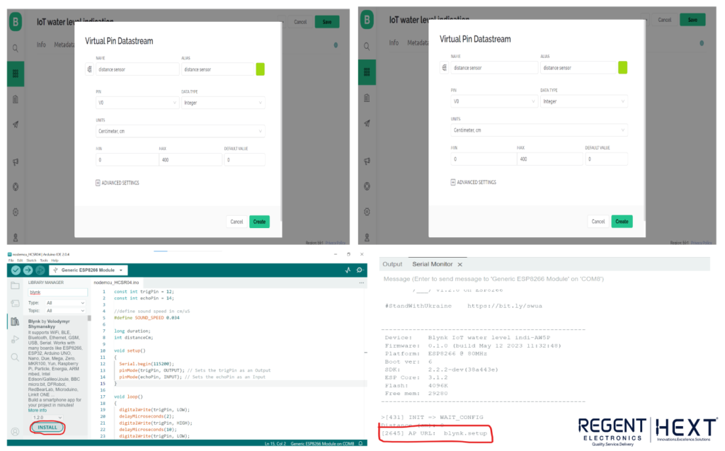
- Create a virtual pin in Blynk to store the distance (water level) data.
- Set the range to 0-400 cm, which is the maximum measurement range for the HC-SR04.
Setting Up Arduino IDE for NodeMCU
To start using NodeMCU with Arduino IDE, follow these steps:
- Install the Blynk library in the Arduino IDE.
- Set up your NodeMCU in Arduino IDE by selecting the appropriate board and port.
- Write the code to connect NodeMCU to Wi-Fi and send data to the Blynk platform.
Here’s an example code to get you started:
#define BLYNK_TEMPLATE_ID “YourTemplateID”
#define BLYNK_TEMPLATE_NAME “WaterLevelIndicator”
#define BLYNK_FIRMWARE_VERSION “0.1.0”
#define BLYNK_PRINT Serial
#include “BlynkEdgent.h”
BlynkTimer timer;
const int trigPin = 12;
const int echoPin = 14;
#define SOUND_SPEED 0.034 // Speed of sound in cm/uS
long duration;
int distanceCm;
void myTimer() {
Blynk.virtualWrite(V0, distanceCm);
delay(1000);
}
void setup() {
Serial.begin(115200);
pinMode(trigPin, OUTPUT);
pinMode(echoPin, INPUT);
delay(100);
timer.setInterval(1000L, myTimer);
BlynkEdgent.begin();
}
void loop() {
digitalWrite(trigPin, LOW);
delayMicroseconds(2);
digitalWrite(trigPin, HIGH);
delayMicroseconds(10);
digitalWrite(trigPin, LOW);
duration = pulseIn(echoPin, HIGH);
distanceCm = duration * SOUND_SPEED / 2;
Serial.print(“Distance (cm): “);
Serial.println(distanceCm);
delay(500);
BlynkEdgent.run();
timer.run();
}
Blynk Mobile App Setup
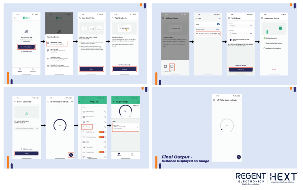
- Download the Blynk mobile app (available for Android and iOS).
- In the app, add a new device and search for nearby devices.
- Connect the device to your Wi-Fi network, and Blynk will automatically pair the device.
- Add a gauge widget to the dashboard to display the water level.
Final Setup and Monitoring
Once your IoT water level indicator is connected and the device is online, you can monitor the water level in real-time using the Blynk app on your smartphone. You can also view the data on the Blynk Web Dashboard, providing remote access to the water level.
Conclusion
With this setup, you’ve successfully built an IoT water level indicator using NodeMCU and the HC-SR04 ultrasonic sensor. You can monitor water levels remotely via the Blynk app or web dashboard. This system can be adapted to various fluid types, providing a flexible and scalable solution for water management.
If you have any questions or need assistance, feel free to leave a comment below.