
Water Level Indicator: Interfacing with Arduino – Connection and Code
Introduction
The water level indicator using Arduino is a compact water management system designed to help users efficiently monitor water levels in storage tanks. This step-by-step guide will assist you in building a water level indicator to optimize water usage.
By implementing this system, you can determine the exact amount of water required, preventing unnecessary wastage and ensuring optimal water conservation.
Importance of a Water Level Indicator
Water scarcity is a pressing issue in many parts of the world, and proper water management at an individual level is essential. One effective way to achieve this is by integrating a water level indicator in your water storage system.
A water level sensor can provide real-time monitoring, allowing you to turn your water pump ON/OFF based on the detected water level. This not only prevents water wastage but also ensures a steady water supply.
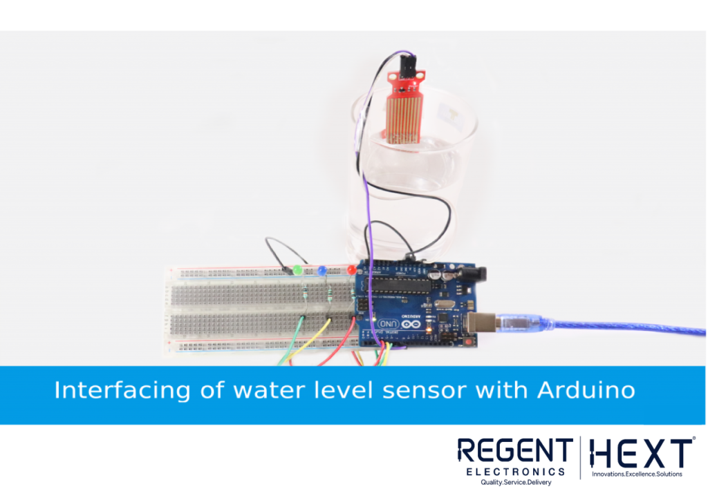
In this tutorial, we will interface a water level sensor with Arduino UNO to measure the water level in a storage tank. When the water level drops below a set threshold, the pump will automatically turn ON. Conversely, when the tank is full, the system will turn OFF the pump.
Why Do You Need a Water Level Indicator?
Many times, it is difficult to determine the water level inside a tank just by looking from the outside. As a result, water pumps are often left running for extended periods, leading to excessive water wastage.
With this project, you can:
- Monitor the water level in your tank accurately.
- Control the water pump efficiently.
- Avoid overflows and shortages.
- Use LED indicators to display different water levels visually.
Now, let’s explore the components and working mechanism of the water level indicator system.
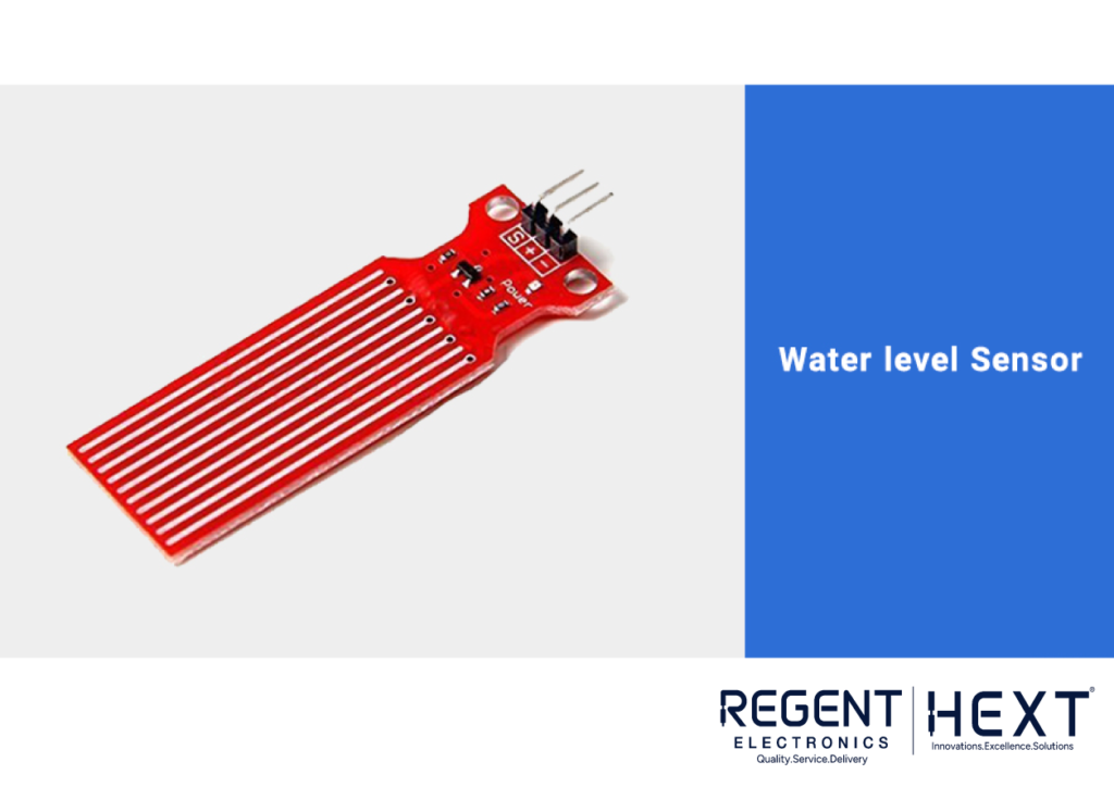
Understanding the Water Level Sensor
Hardware Overview
The water level sensor used in this project consists of multiple exposed copper traces arranged in a sequence. These traces function as conductivity probes, detecting varying water levels.
Working Principle
The sensor operates based on variable resistance. It contains multiple parallel conductors that act as a resistor whose resistance varies depending on the water level.
- When more of the sensor is submerged in water, conductivity increases, and resistance decreases.
- When less of the sensor is submerged, conductivity decreases, and resistance increases.
The sensor outputs a voltage signal corresponding to the detected resistance, allowing us to measure the water level in real-time.
Pin Configuration
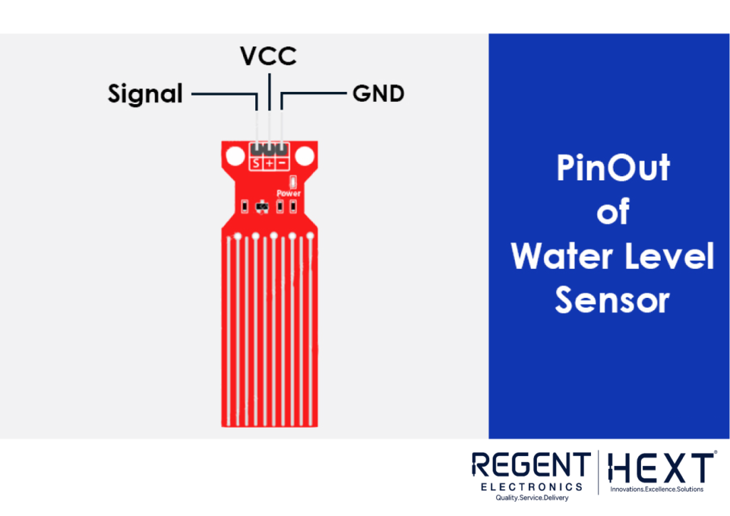
- S (Signal Pin): Analog output connected to the Arduino’s A0 pin.
- +VCC (Power Pin): Requires 3.3V – 5V supply.
- GND (Ground Pin): Connects to the ground terminal of the Arduino.
Required Components
To build this project, you will need the following components:
- Water level sensor
- Arduino Uno
- Connecting wires
- LEDs (Red, Yellow, Green)
- Resistors
- Breadboard
Calibrating the Water Level Sensor

To ensure accurate readings, it is important to calibrate the water level sensor. Before starting the project, note the output values when the sensor is:
- Completely dry.
- Partially submerged.
- Fully submerged.
By doing some trial and error, you will be able to determine the threshold values for different water levels. Once calibrated, your system will provide reliable water level monitoring.
Interfacing Diagram
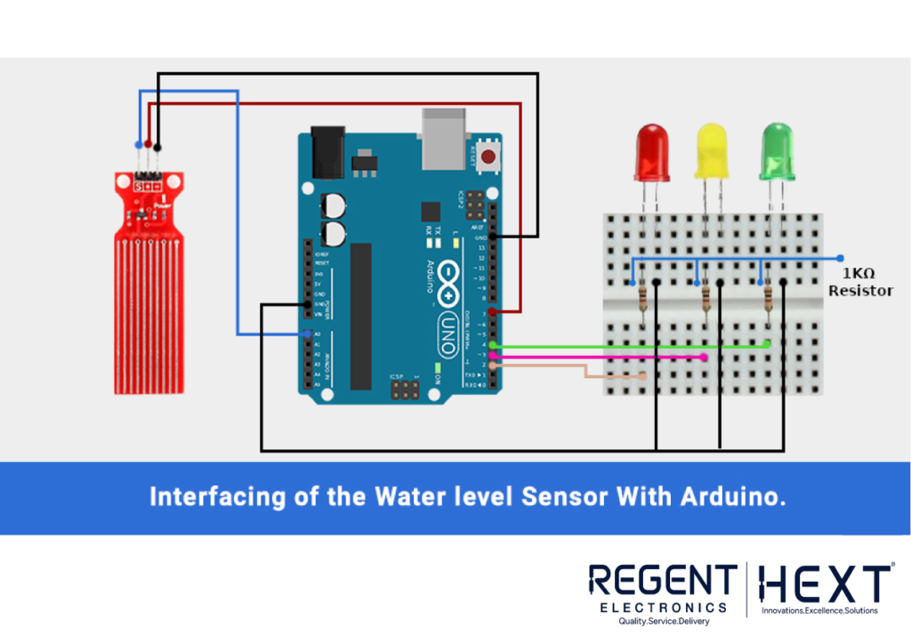
Follow these steps to connect the components:
- Signal pin (S) → Connect to A0 (Analog Input) of Arduino.
- VCC pin → Connect to Digital Pin 7 of Arduino.
- GND pin → Connect to GND of Arduino.
- LEDs (Red, Yellow, Green) → Connect to Digital Pins 2, 3, and 4 respectively.
- Common anode of LEDs → Connect to GND.
Arduino Code for Water Level Indicator
Once the circuit is assembled, upload the following code to your Arduino IDE.
/* Adjust these values based on calibration */
int lowerThreshold = 420;
int upperThreshold = 520;
// Sensor pins
#define sensorPower 7
#define sensorPin A0
// Variable to store water level
int val = 0;
// LED pins
int redLED = 2;
int yellowLED = 3;
int greenLED = 4;
void setup() {
Serial.begin(9600);
pinMode(sensorPower, OUTPUT);
digitalWrite(sensorPower, LOW);
// Set LED pins as output
pinMode(redLED, OUTPUT);
pinMode(yellowLED, OUTPUT);
pinMode(greenLED, OUTPUT);
// Turn off all LEDs initially
digitalWrite(redLED, LOW);
digitalWrite(yellowLED, LOW);
digitalWrite(greenLED, LOW);
}
void loop() {
int level = readSensor();
if (level == 0) {
Serial.println(“Water Level: Empty”);
digitalWrite(redLED, LOW);
digitalWrite(yellowLED, LOW);
digitalWrite(greenLED, LOW);
}
else if (level > 0 && level <= lowerThreshold) {
Serial.println(“Water Level: Low”);
digitalWrite(redLED, HIGH);
digitalWrite(yellowLED, LOW);
digitalWrite(greenLED, LOW);
}
else if (level > lowerThreshold && level <= upperThreshold) {
Serial.println(“Water Level: Medium”);
digitalWrite(redLED, LOW);
digitalWrite(yellowLED, HIGH);
digitalWrite(greenLED, LOW);
}
else if (level > upperThreshold) {
Serial.println(“Water Level: High”);
digitalWrite(redLED, LOW);
digitalWrite(yellowLED, LOW);
digitalWrite(greenLED, HIGH);
}
delay(1000);
}
int readSensor() {
digitalWrite(sensorPower, HIGH);
delay(10);
val = analogRead(sensorPin);
digitalWrite(sensorPower, LOW);
return val;
}
Conclusion
This guide has provided a comprehensive overview of how to build a water level indicator using Arduino. By implementing this project, you can effectively monitor and control water levels in your storage tank, preventing wastage and ensuring efficient water management.
If you found this tutorial helpful, feel free to share your thoughts in the comment section. Let’s work together towards better water conservation with Regent Electronics!