
Build a Servo Control System Using Raspberry Pi Pico and Servo Motor
Looking to build your own servo control system for a DIY robotics or electronics project? With a Raspberry Pi Pico and a simple servo motor, you can easily set up a basic yet powerful servo control system to rotate and position objects with high accuracy.
In this blog by Regent Electronics, we’ll guide you through how to connect, program, and control a servo motor using Raspberry Pi Pico and MicroPython. This is a perfect beginner-friendly project to understand how PWM (Pulse Width Modulation) works and how servos respond to different signals.
What is a Servo Motor?
A servo motor is an actuator used for precise control of angular or linear position, velocity, and acceleration. It features a rotary encoder or potentiometer for feedback, and an internal gearbox to increase torque. The motor locks in at a desired angle when provided with the correct control signal, typically in the form of a PWM signal.
✅ Common Applications of Servo Motors:
- Robotic Arms – For controlling arm joints and movement angles
- Camera Auto-Focus Systems – For adjusting lens positions automatically
- CNC & Metal Cutting Machines – Precision control in machinery
- RC Cars & Drones – Steering or actuator control via remote
Depending on the application, servo motors come in different types—industrial servos for high torque and precision, and hobby servos for low-cost DIY and prototyping.
Servo Motor Used in This Project: SG90
For this project, we’re using the SG90 servo motor, a popular and affordable hobby servo with the following specifications:
- Torque: 2.5 kg/cm
- Speed: 0.1 sec/60°
- Operating Voltage: 5V
Required Components
Gather the following components before getting started:
| Component | Quantity |
| Raspberry Pi Pico | 1 |
| USB Cable (for Pico) | 1 |
| SG90 Servo Motor | 1 |
| Jumper Wires (M to F) | 3 |
Circuit Connections
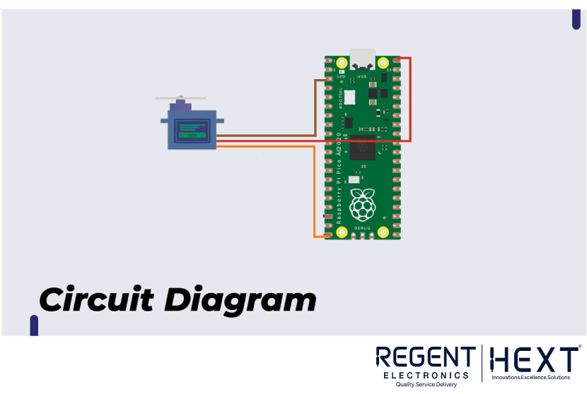
Connect the SG90 servo motor to your Raspberry Pi Pico as follows:
| SG90 Wire | Connects To Raspberry Pi Pico |
| Red | VBUS (5V Power) |
| Brown | GND |
| Orange | GPIO15 (PWM Signal) |
🔧 Tip: All GPIO pins on the Raspberry Pi Pico support PWM, so you can use any PWM-capable pin.
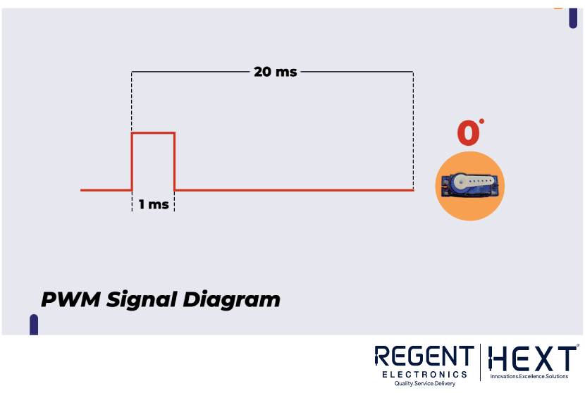
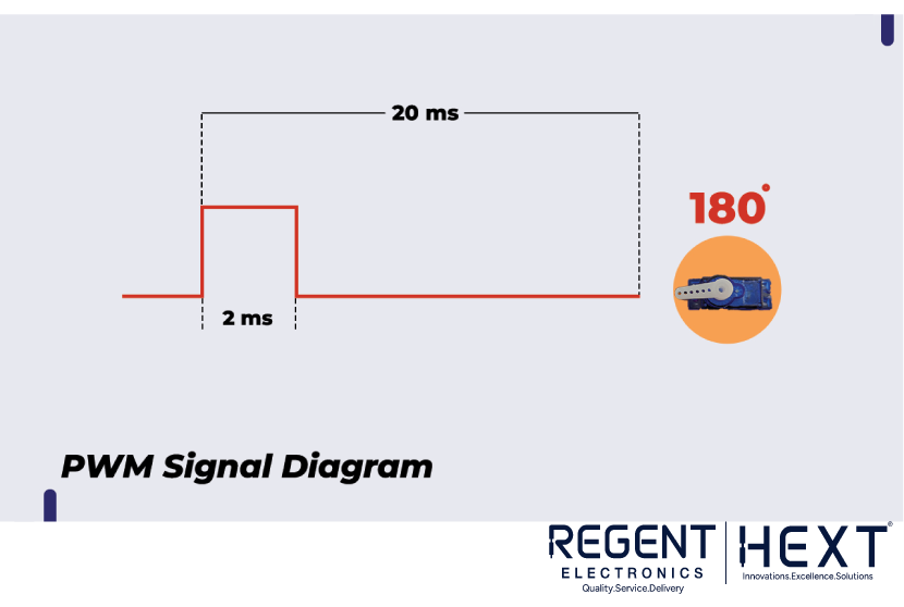
How PWM Controls the Servo Angle
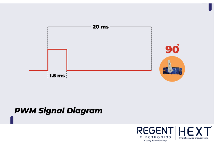
A servo motor’s shaft position is controlled via PWM signals. The standard PWM period is 20ms, equivalent to 50Hz frequency.

| On-Time (ms) | Shaft Angle |
| 1.0 ms | 0° |
| 1.5 ms | 90° |
| 2.0 ms | 180° |
To generate these signals using MicroPython on the Pico, we must convert time into values supported by the pwm.duty_u16() function, which accepts values from 0 to 65535.
Example Calculation:
- For 1ms on-time:
(65535 * 1) / 20 = 3277 - For 2ms on-time:
(65535 * 2) / 20 = 6554
However, in real-world usage with the SG90, we found:
- 1800 = 0°
- 8000 = 180°
This means there’s a range of 6200 values, and every degree equals about 34.45 units.
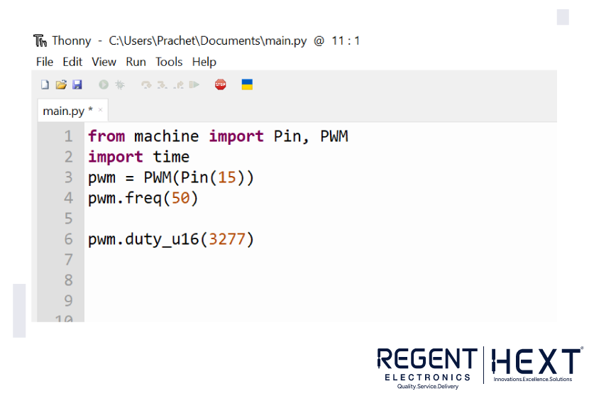
MicroPython Code: Basic PWM Setup

Here’s a simple code snippet to generate a 1ms PWM signal using Raspberry Pi Pico:
python
CopyEdit
from machine import Pin, PWM
import time
servo = PWM(Pin(15))
servo.freq(50)
# Set duty cycle for 0 degree position
servo.duty_u16(1800)
Create a Function for Angle Control
To control the servo position based on angle input, define a function:
python
CopyEdit
def set_angle(angle):
duty = int(1800 + (angle * 34.45))
servo.duty_u16(duty)
# Example usage
set_angle(90) # Moves servo to 90 degrees
Final Thoughts
With just a Raspberry Pi Pico and an SG90 servo motor, you can build your own servo control system and rotate the shaft to any angle between 0° and 180°. This project is a great way to learn about PWM, servo behavior, and embedded programming.
If you have any questions or need help troubleshooting, feel free to leave a comment. The Regent Electronics team is here to support you!