

Orange Raspberry Pi Pico Advanced Kit
Introduction
Welcome back! In this blog, we will explore the Orange Raspberry Pi Pico Advanced Kit, available exclusively at Regent Electronics. This kit includes a variety of components designed to enhance your understanding of the Raspberry Pi Pico board.
In our previous blog, we covered the installation process and fundamental topics. If you haven’t checked it out yet, we recommend doing so to build a solid foundation. Today, we’ll dive into advanced concepts and practical applications of the Raspberry Pi Pico.
To facilitate learning, this blog is structured into sections, starting with basic concepts and gradually progressing to more advanced topics.
Interfacing a PIR Sensor with Raspberry Pi Pico
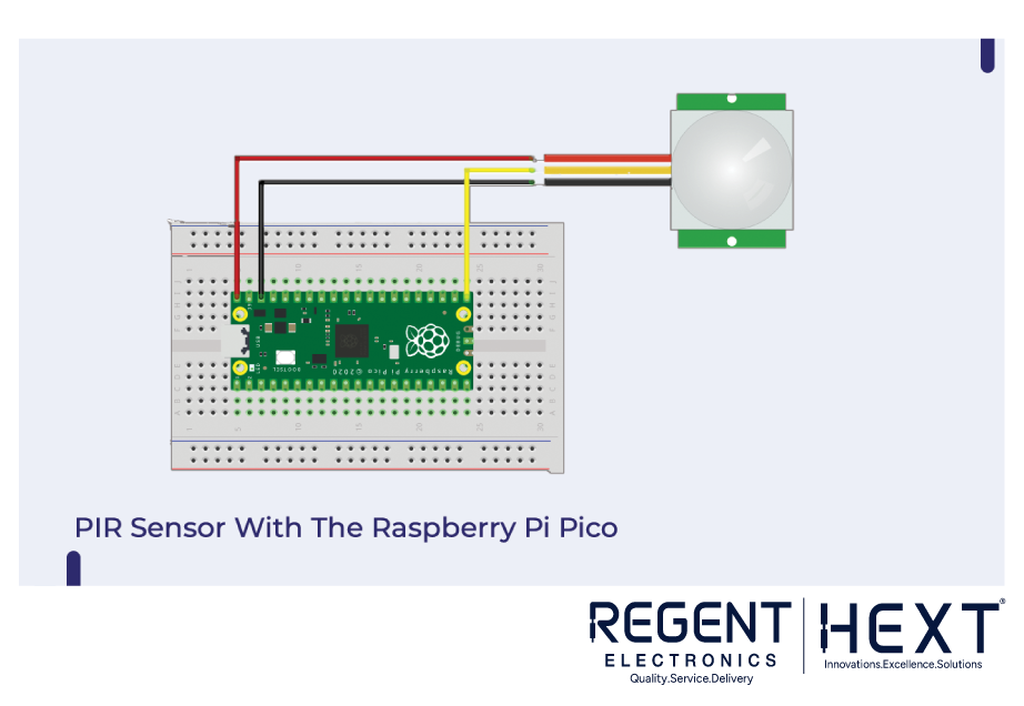
A PIR (Passive Infrared) sensor is widely used in security systems to detect motion. It works by sensing infrared radiation from objects in its field of view.
How the PIR Sensor Works
A PIR sensor consists of two pyroelectric material slots that detect temperature changes. When a warm object (such as a person) moves in front of the sensor, it generates a differential voltage, which the microcontroller processes to trigger an action.
Connecting the PIR Sensor to Raspberry Pi Pico
The PIR sensor has three pins:
- Signal: Connect to any GPIO pin on the Raspberry Pi Pico
- VCC: Connect to 3.3V or 5V power supply
- GND: Connect to ground
Python Code for PIR Sensor
from machine import Pin
import utime
pir_sensor = Pin(16, Pin.IN)
utime.sleep(2)
while True:
if pir_sensor.value() == 1:
print(“Motion Detected”)
utime.sleep(3)
else:
print(“No Motion”)
utime.sleep(1)
Upload the above code to your Raspberry Pi Pico, and the PIR sensor will start detecting motion.
Interfacing a Buzzer with Raspberry Pi Pico
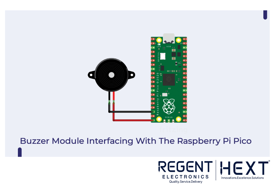
This kit includes an active buzzer, which generates sound signals when activated.
Connecting the Buzzer Module
The buzzer has two pins:
- Negative (-): Connect to GND
- Positive (+): Connect to any GPIO pin
Python Code for Buzzer
from machine import Pin
import time
buzzer = Pin(15, Pin.OUT)
while True:
buzzer.value(1)
time.sleep(1)
buzzer.value(0)
This code activates the buzzer when triggered.
Controlling a 16 RGB LED Ring with Raspberry Pi Pico
RGB LED rings can create stunning visual effects by controlling individual LEDs.
Connecting the RGB LED Ring
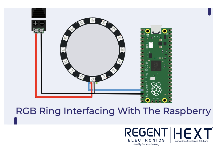
The RGB LED ring has three main pins:
- Data: Connect to any GPIO pin
- VCC: Connect to power
- GND: Connect to ground
Python Code for RGB LED Ring
import array, time
from machine import Pin
import rp2
led_count = 16
PIN_NUM = 13
brightness = 1.0
@rp2.asm_pio(sideset_init=rp2.PIO.OUT_LOW, out_shiftdir=rp2.PIO.SHIFT_LEFT,
autopull=True, pull_thresh=24)
def ws2812():
wrap_target()
label(“bitloop”)
out(x, 1) .side(0)
jmp(not_x, “do_zero”) .side(1)
jmp(“bitloop”) .side(1)
label(“do_zero”)
nop() .side(0)
wrap()
This code controls the brightness and patterns of the LEDs.
Using a Dot Matrix Display with Raspberry Pi Pico

Dot matrix displays are commonly used for scrolling messages and digital signage.
Connecting the Dot Matrix Display
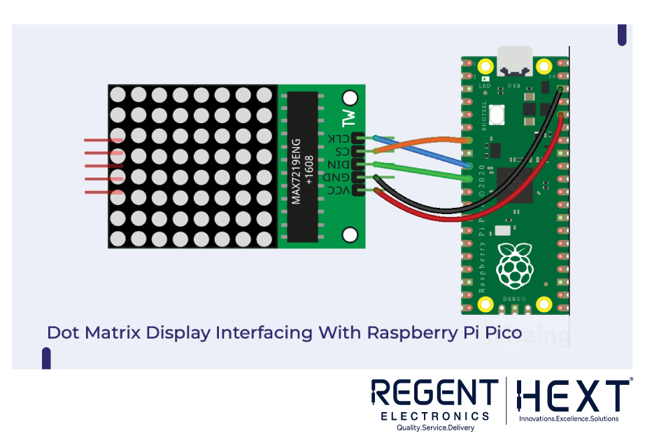
- VCC & GND: Connect to power and ground
- Data, Clock, CS: Connect to respective GPIO pins
Python Code for Dot Matrix Display
from machine import Pin, SPI, ADC
import max7219
from utime import sleep
spi = SPI(0)
display = max7219.Matrix8x8(spi=spi, cs=Pin(5), num=4)
display.brightness(2)
display.text(“Hello”, 0, 1, 1)
display.show()
This code displays text on the dot matrix screen.
Interfacing an I2C LCD with Raspberry Pi Pico
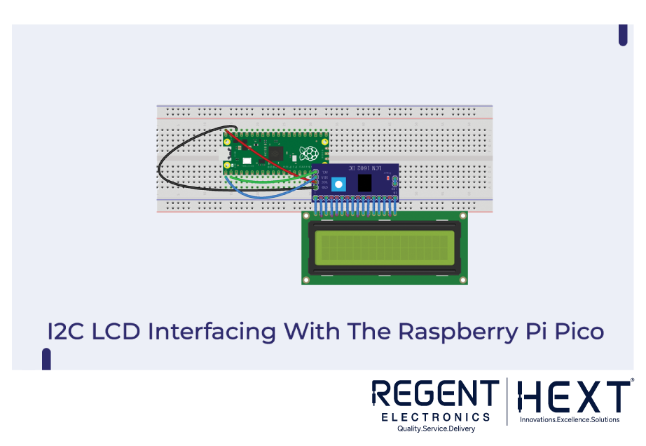
Connecting the I2C LCD
- SDA & SCL: Connect to I2C ports of Raspberry Pi Pico
- VCC & GND: Connect to power and ground
Python Code for I2C LCD
from machine import I2C, Pin
from time import sleep
from pico_i2c_lcd import I2cLcd
i2c = I2C(0, sda=Pin(0), scl=Pin(1), freq=400000)
I2C_ADDR = i2c.scan()[0]
lcd = I2cLcd(i2c, I2C_ADDR, 2, 16)
lcd.putstr(“Hello from Regent Electronics”)
This code displays a message on the LCD.
Controlling a Servo Motor with Raspberry Pi Pico

Servo motors allow precise control over angular movement.
Connecting the Servo Motor
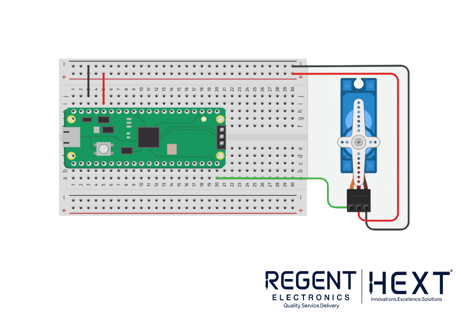
- Signal: Connect to any GPIO pin
- VCC & GND: Connect to power and ground
Python Code for Servo Motor
from machine import Pin, PWM
import utime
pwm = PWM(Pin(0))
pwm.freq(50)
while True:
pwm.duty_ns(100000)
utime.sleep(1)
pwm.duty_ns(200000)
utime.sleep(1)
This code moves the servo motor between positions.
Conclusion
We have explored essential interfacing techniques and coding for various modules included in the Orange Raspberry Pi Pico Advanced Kit. If you have any questions, feel free to leave them in the comments section. Happy coding!