
Orange Raspberry Pi Pico Intermediate Kit
Introduction to Orange Raspberry Pi Pico Intermediate Kit
The Raspberry Pi Pico board is a compact, high-performance microcontroller that has gained immense popularity in the IoT sector. Its small size and efficiency make it an excellent choice for various applications.
In this blog, we will explore how to connect various sensors and components to the Raspberry Pi Pico board using the Python programming language and the Thonny IDE. If you are new to Python, don’t worry! The accompanying booklet contains all the essential information you need to get started.
Now, let’s dive into the interfacing of an LED with the Raspberry Pi Pico.
Interfacing an LED and Switch with Raspberry Pi Pico
Previously, we learned how to blink the onboard LED. In this section, we will connect an external LED to the Raspberry Pi Pico and control it using a switch.
Understanding LEDs and Switches
An LED (Light Emitting Diode) emits light when voltage is applied across its anode and cathode terminals. When VCC is connected to the anode and GND to the cathode, the LED glows.
Switches are electronic components used to establish or break connections between two points. There are different types of switches available, each serving various purposes.
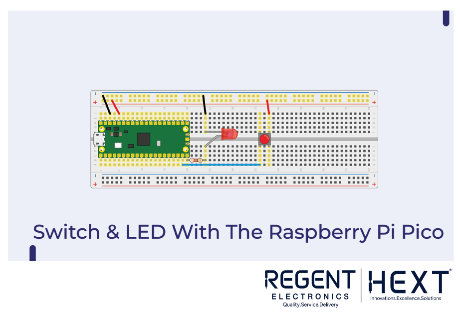
Circuit Diagram for Interfacing LED and Switch with Raspberry Pi Pico
Before proceeding, ensure you connect the components correctly. Use a 320-ohm resistor to protect the LED from overcurrent, as excessive current can burn it out.
Note: Failure to use a resistor may damage your Raspberry Pi Pico board.
Python Code for LED and Switch Control
from machine import Pin
import time
led = Pin(15, Pin.OUT)
button = Pin(14, Pin.IN, Pin.PULL_DOWN)
while True:
if button.value():
led.toggle()
time.sleep(0.5)
By running this code, pressing the button will toggle the LED on and off.
Interfacing an RGB Module with Raspberry Pi Pico
Unlike single-color LEDs, an RGB module can emit different colors using three pins: Red, Green, and Blue.
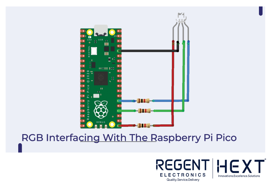
Wiring RGB Module with Raspberry Pi Pico
- GPIO16 → Red Pin of RGB
- GPIO18 → Green Pin of RGB
- GPIO20 → Blue Pin of RGB
- GND → Ground of RGB
Python Code for RGB LED Control
from machine import Pin
import utime
red = Pin(16, Pin.OUT)
green = Pin(18, Pin.OUT)
blue = Pin(20, Pin.OUT)
while True:
red.value(1)
green.value(1)
blue.value(1)
utime.sleep(1)
red.value(0)
green.value(1)
blue.value(1)
utime.sleep(1)
red.value(1)
green.value(0)
blue.value(1)
utime.sleep(1)
red.value(1)
green.value(1)
blue.value(0)
utime.sleep(1)
Uploading this code will allow the RGB module to emit different colors.
Interfacing an IR Module and Buzzer with Raspberry Pi Pico
IR Modules are used for proximity sensing and obstacle detection. They contain an IR transmitter, detector, and a control circuit.
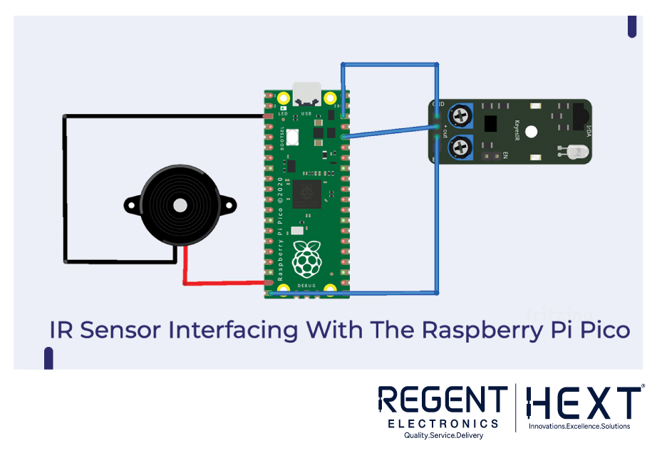
Wiring IR Module and Buzzer to Raspberry Pi Pico
- Signal Pin (IR Module) → GPIO pin
- VCC (IR Module) → 3.3V of Raspberry Pi Pico
- GND (IR Module) → GND of Raspberry Pi Pico
- Signal Pin (Buzzer) → GPIO pin 18
- VCC (Buzzer) → 3.3V of Raspberry Pi Pico
- GND (Buzzer) → GND of Raspberry Pi Pico
Python Code for IR Module and Buzzer
from machine import Pin
import utime
buzzer = Pin(16, Pin.OUT)
sensor = Pin(15, Pin.IN, Pin.PULL_DOWN)
while True:
print(sensor.value())
if sensor.value() == 1:
buzzer.value(0)
else:
buzzer.toggle()
utime.sleep(0.5)
This code allows the buzzer to beep when an obstacle is detected.
Conclusion
Through this blog, we have learned how to interface various electronic components with the Raspberry Pi Pico board, define pin modes, and implement basic projects using Python. If you have any doubts, feel free to drop a comment. Stay tuned for more exciting tutorials from Regent Electronics!