

Build Your Own Servo Control System with Raspberry Pi Pico
Servo motors play a crucial role in applications requiring precise steering and position control. These motors come with a rotary encoder for accurate angle locking and an inbuilt gearbox that enhances torque. In this blog, we will explore how to create a servo control system using Raspberry Pi Pico.
Applications of Servo Motors
Servo motors are widely used in various industries and DIY projects. Some common applications include:
- Robotic Arms – Used to control movement angles in robotic arms.
- Camera Systems – Enables auto-focusing for precision imaging.
- CNC and Metal Machinery – Found in cutting and machining tools.
- Remote Control Models – Powers mechanical movements in RC cars and airplanes.
There are different types of servo motors, depending on the application. Industrial-grade servo motors offer high torque and precision, while hobby servo motors are ideal for DIY projects.
Choosing the Right Servo Motor
For this project, we are using the SG90 servo motor, an excellent choice for beginners due to its ease of use and affordability. Key specifications of the SG90 include:
- Torque: 2.5kg/cm
- Speed: 0.1 sec/60 degrees
- Operating Voltage: 5V
To control the shaft’s angular position, we send a PWM (Pulse Width Modulation) signal to the orange wire of the servo motor.
Components Required
To build the servo control system, gather the following components:
- Raspberry Pi Pico
- USB Cable
- SG90 Servo Motor
- Jumper Wires (M to F) – 3 pieces
Circuit Connection
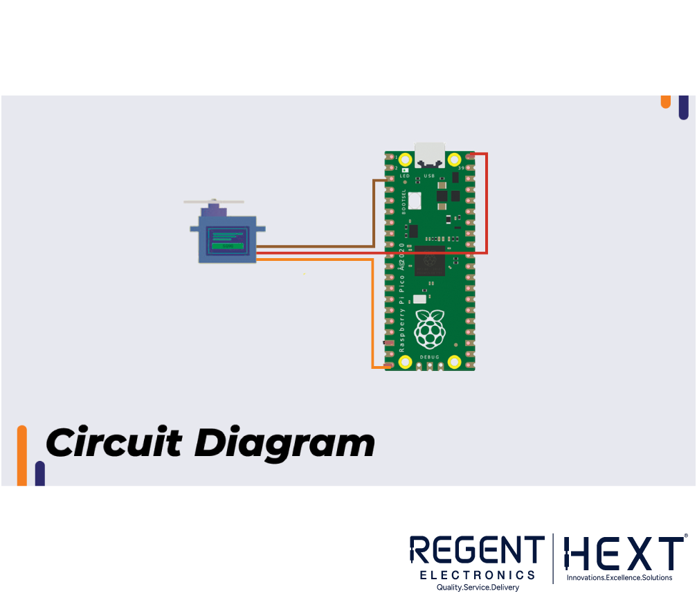
- The servo motor operates at 5V, which is supplied through the VBus pin of the Raspberry Pi Pico.
- The red wire of the servo connects to the VBus pin.
- The brown wire (ground) connects to Pin 3 (GND).
- The orange wire, carrying the PWM signal, is connected to PWM Pin 15 of the Raspberry Pi Pico.
All GPIO pins on the Raspberry Pi Pico support PWM, meaning you can connect the servo motor to any available pin.
Generating the PWM Signal for the Servo Motor

According to the SG90 servo motor datasheet, the PWM signal operates as follows:
- PWM Period: 20ms (50Hz frequency)
- 1ms On-Time → 0-degree position
- 1.5ms On-Time → 90-degree position
- 2ms On-Time → 180-degree position


The duty cycle is calculated using the formula:
(65535 * On-Time) / 20ms
For example:
- 1ms On-Time → 3277
- 1.5ms On-Time → 4915
- 2ms On-Time → 6553
However, these values may slightly vary based on the servo motor’s calibration.
Raspberry Pi Pico PWM Code
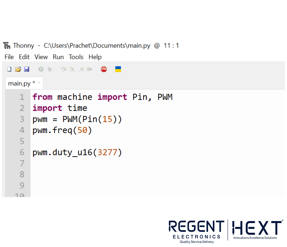
Below is the Python code to generate a 50Hz PWM signal for controlling the servo motor using Raspberry Pi Pico:
from machine import Pin, PWM
import time
servo = PWM(Pin(15)) # PWM Pin 15
servo.freq(50) # Set frequency to 50Hz
def set_angle(angle):
duty = int((angle * 34.45) + 1800) # Calculate duty cycle
servo.duty_u16(duty)
time.sleep(0.5) # Small delay for motor to reach the position
# Example usage
set_angle(0) # Move to 0 degrees
set_angle(90) # Move to 90 degrees
set_angle(180) # Move to 180 degrees

Understanding the Code
- The PWM function is assigned to Pin 15.
- The frequency is set to 50Hz (standard for servo motors).
- The set_angle() function calculates the required duty cycle for a given angle.
- The function accepts an angle from 0 to 180 degrees, converts it into a PWM signal, and moves the servo accordingly.
Conclusion
By following this guide, you can create a fully functional servo control system using Raspberry Pi Pico. This project is a great introduction to PWM signals, servo motors, and microcontroller programming. If you have any questions, feel free to leave a comment, and our team at Regent Electronics will be happy to assist you!