

DIY Hand Gesture Controlled Robo Car: A Complete Guide
In this innovative tutorial, you will learn how to build a Hand Gesture Controlled Robot Car using an Arduino board, MPU6050 sensor, RF Transmitter-Receiver modules, and L293D Motor Driver. This project enables you to control your robot car with hand gestures, making it a fun and engaging way to interact with technology.
Components Required
- Arduino Board
- Breadboard
- RF Transmitter-Receiver Pair (FS1000A)
- L293D Motor Driver
- MPU6050 Gyroscope Sensor
- Battery
- Connecting Wires
- Robo Car Chassis
- HT12D IC
- HT12E IC
- DIP Switch
What is the FS1000A RF Module?
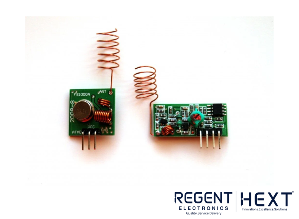
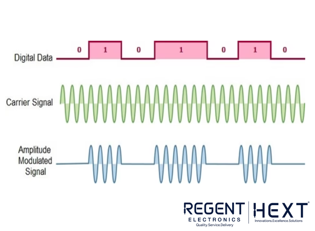
The FS1000A is a 433 MHz RF Transmitter and Receiver module that allows for wireless communication between devices. The transmitter sends data, while the receiver picks it up. This setup uses Amplitude Shift Keying (ASK) modulation, where the carrier wave’s amplitude changes according to the input data, making it an efficient way to transmit binary data.
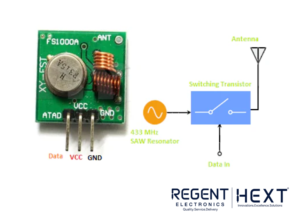
- RF Transmitter (FS1000A): This module has an oscillator and simple passive components that generate a carrier wave. The data signal modulates the wave, transmitting information wirelessly.
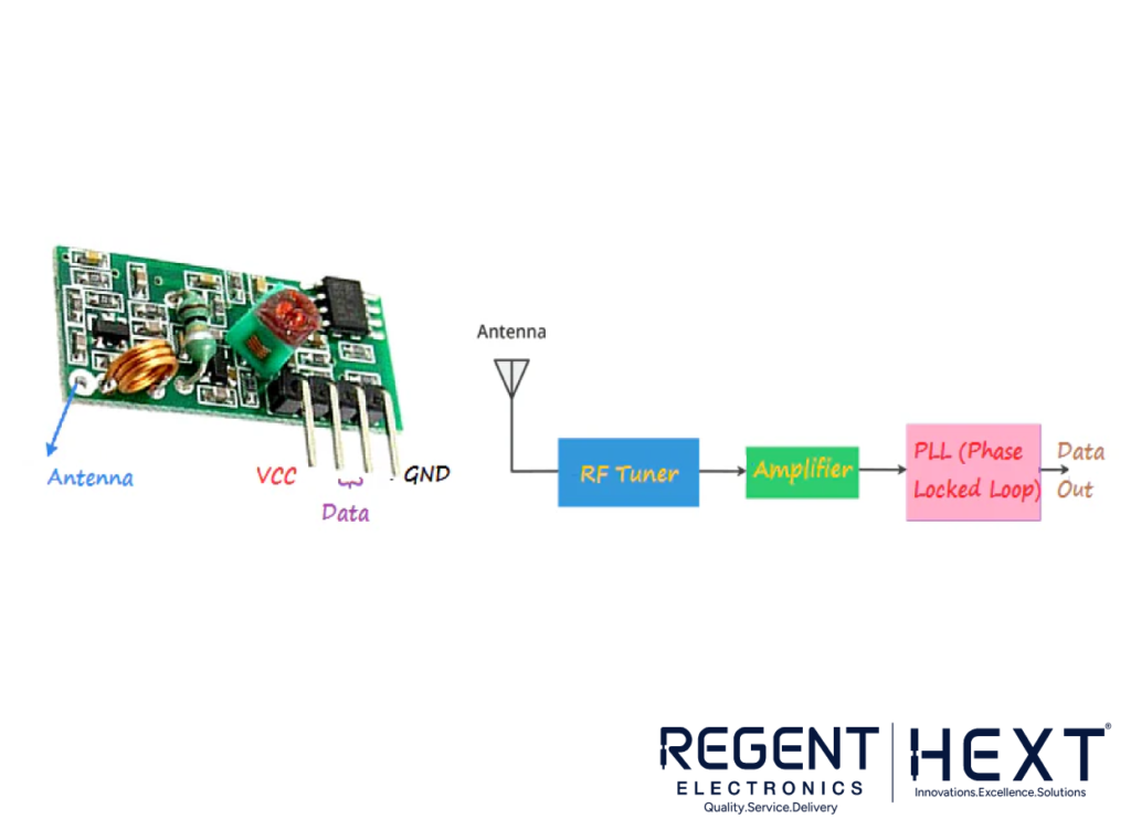
- RF Receiver (XY-MK-5V): This module amplifies the received signal and decodes the data back into a usable form for the robot.
What is the HT12E and HT12D IC?

These Encoder and Decoder ICs are essential for converting data into formats suitable for transmission and reception.
- HT12E (Encoder): This IC takes parallel data and converts it into a serial format for transmission via RF.
- HT12D (Decoder): The corresponding decoder receives serial data, converts it back to parallel, and sends it to the motor driver for controlling the motors.
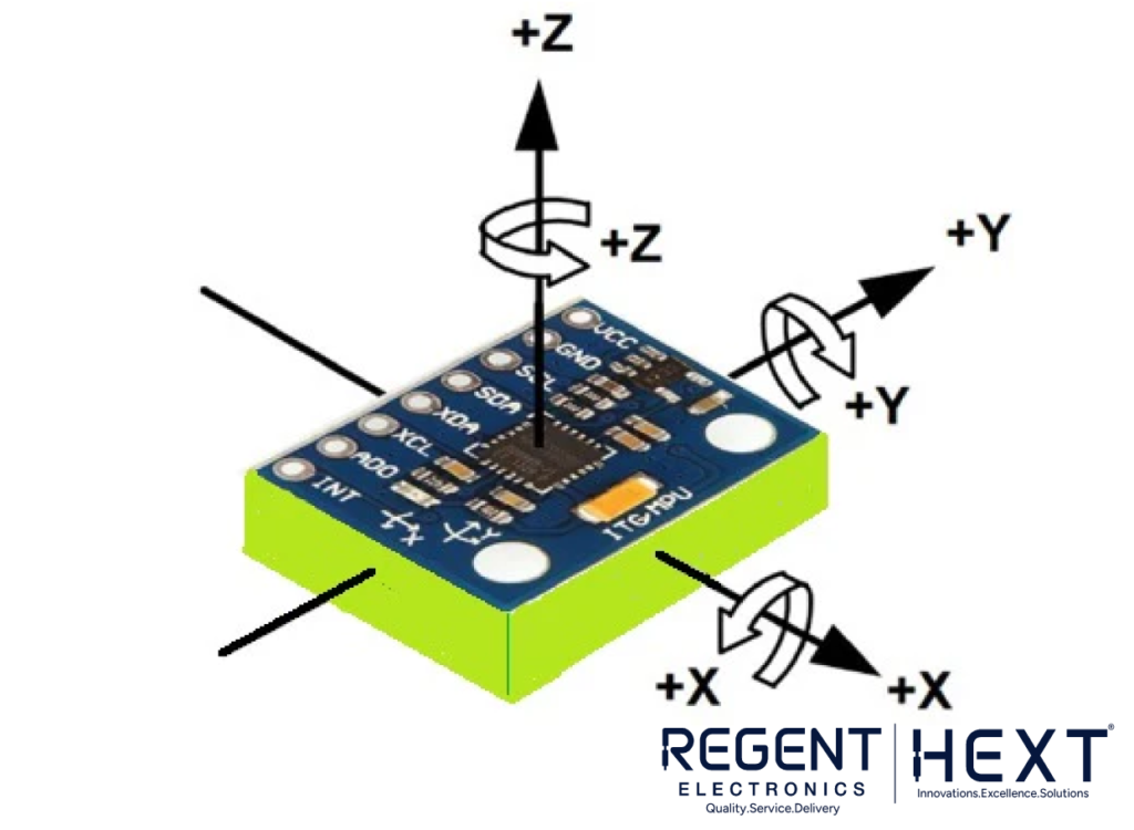
What is the MPU6050 IMU Sensor?
The MPU6050 is a 6-axis motion tracking sensor that integrates a 3-axis accelerometer and a 3-axis gyroscope. This sensor is crucial for detecting hand gestures and orientation. It uses an I2C communication interface to send data to the Arduino.
- Gyroscope: Measures angular velocity, allowing the robot to track rotational movements.
- Accelerometer: Measures linear acceleration along the X, Y, and Z axes, enabling the detection of changes in position.
Controlling Motors with L293D Motor Driver
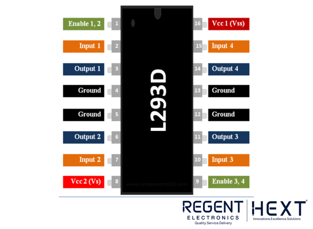
The L293D Motor Driver is used to control the direction and speed of the DC motors. It uses an H-Bridge configuration to change the polarity of the voltage applied to the motors, thus changing their direction.
- Motor Control: The L293D can drive two DC motors, allowing the robot to move in any direction.
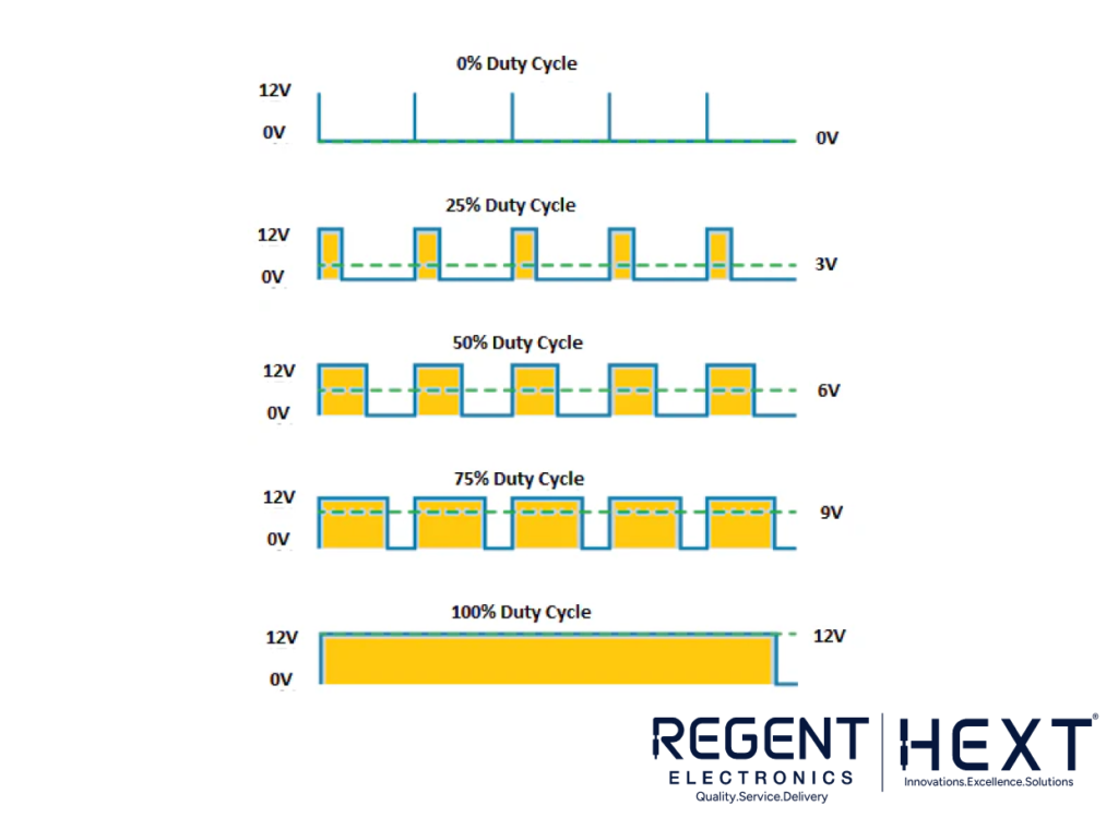
- Speed Control: Pulse Width Modulation (PWM) is used to control the speed of the motors. By varying the duty cycle of the PWM signal, you adjust the average voltage applied to the motors, changing their speed.
Working Principle
The system is divided into two parts: the Transmitter and the Receiver.
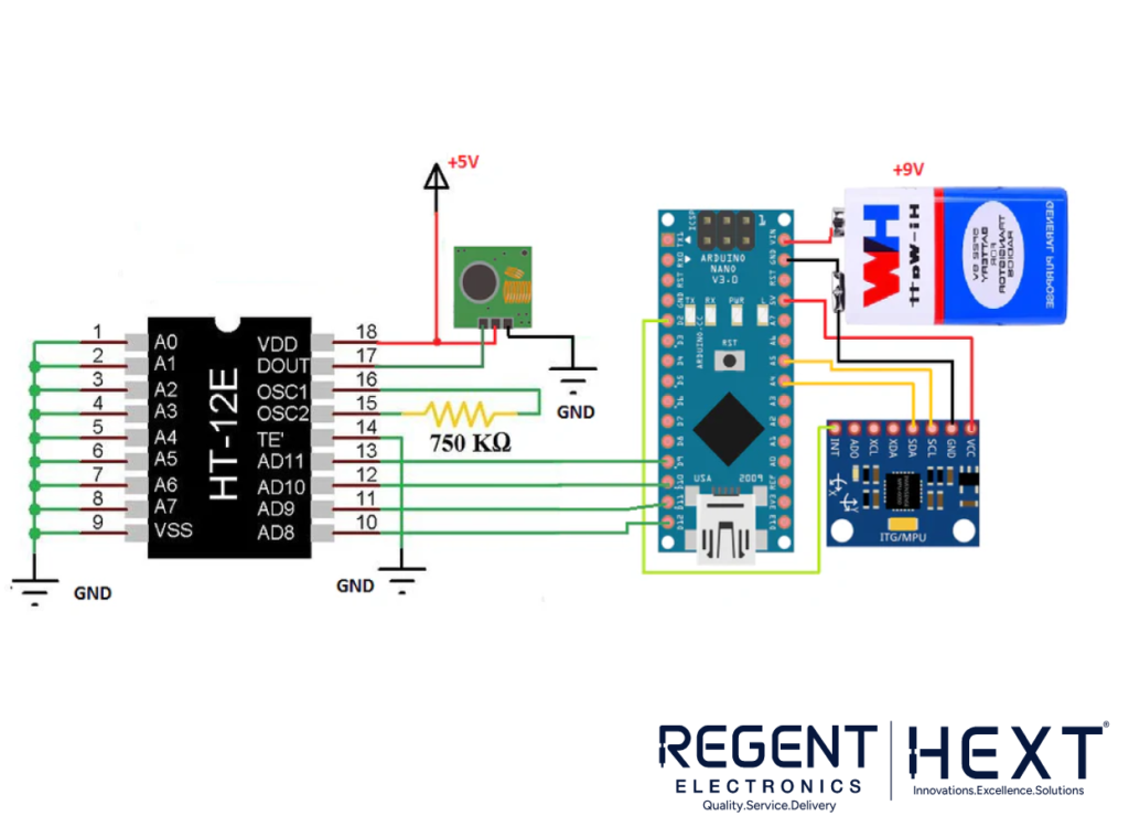
- Transmitter Section: The Arduino constantly reads data from the MPU6050 sensor, which detects hand gestures based on the orientation of the sensor. This data is processed by the HT12E Encoder, which converts it into serial data for transmission via the FS1000A RF Transmitter.
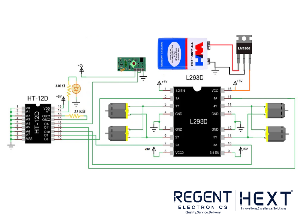
- Receiver Section: The RF Receiver picks up the transmitted serial data, which is then decoded by the HT12D Decoder. The decoded parallel data is sent to the L293D Motor Driver, which controls the DC motors based on the hand gestures.
Gesture-Based Control
The hand gestures, such as tilting or rotating your hand, are detected by the MPU6050. The Arduino interprets these gestures as commands (e.g., move forward, reverse, left, or right) and sends the corresponding data to the receiver section to control the robot’s movements.
Circuit Diagram
The circuit is straightforward:
- The MPU6050 sensor is connected to the Arduino via the I2C interface.
- The HT12E Encoder is connected to the Arduino and transmits the serial data through the FS1000A RF Transmitter.
- The RF Receiver receives the serial data and sends it to the HT12D Decoder, which passes the data to the L293D Motor Driver to control the motors.
Conclusion
This Hand Gesture Controlled Robo Car project is an excellent way to learn about wireless communication, motion sensors, and motor control. By using the MPU6050 sensor, RF communication, and L293D motor driver, you can build a robot that responds to your hand movements, offering a hands-on experience in robotics and IoT technology.
Ready to get started? Build your own gesture-controlled robot car today and enjoy the thrill of controlling technology with just your hands!