

DIY PIR Sensor-Based Burglar Alarm: A Complete Guide
Looking to create your own burglar alarm system using Arduino? This DIY project will guide you through building a simple yet effective security system with the PIR (Passive Infrared) sensor, SIM800L GSM module, and a Piezo buzzer. The system will detect any motion, alert you with a loud sound, and even send an alarm call to your mobile phone, providing added peace of mind when you are away from home.
Components Needed for the DIY Burglar Alarm System
- SIM800L GSM Module
- Arduino Board
- Breadboard
- HC-SR501 PIR Motion Sensor
- Piezo Buzzer
- Connecting Wires
- Power Supply
- DC-DC Buck Converter (LM2596)
- SIM Card
What is the SIM800L GSM Module?
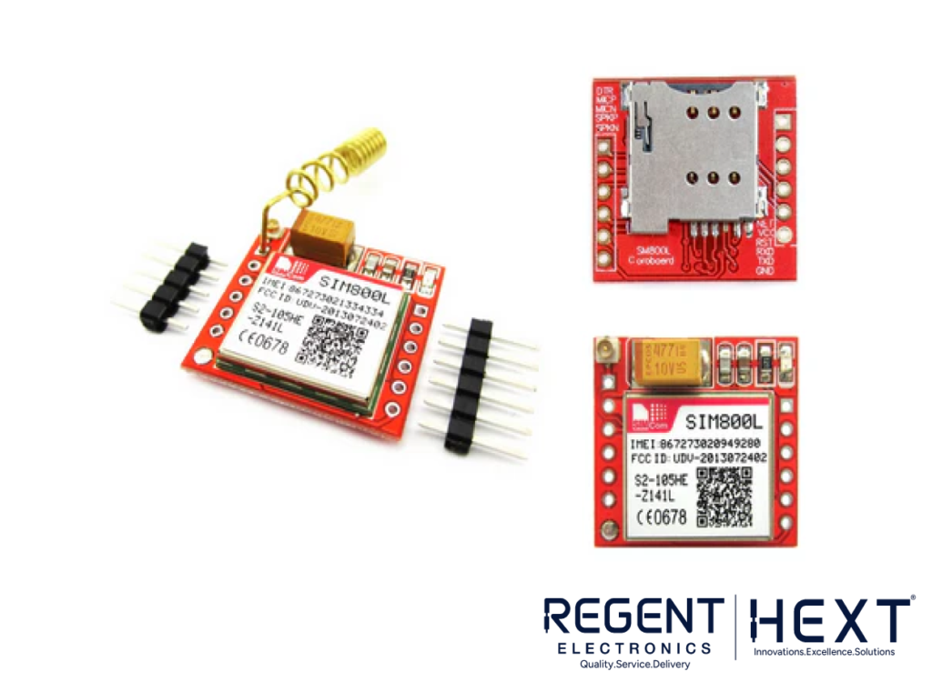
The SIM800L GSM/GPRS module is a compact device that allows your projects to make calls, send SMS, and even connect to the internet. With support for quad-band GSM/GPRS networks, it works worldwide, making it a versatile option for a variety of applications. Here’s how you can use it:
- Voice Calls and SMS: Send and receive messages or make voice calls from your Arduino.
- Power Requirements: The SIM800L operates between 3.4V to 4.4V, with higher power consumption during data transmission (up to 2A), making a reliable power supply essential for the module’s stable operation.
You can power the module using:
- 3.7V Li-Po Battery
- DC-DC Buck Converter (LM2596)
Make sure to properly connect the GND before VCC to avoid damaging the module.
How Does the PIR Motion Sensor Work?
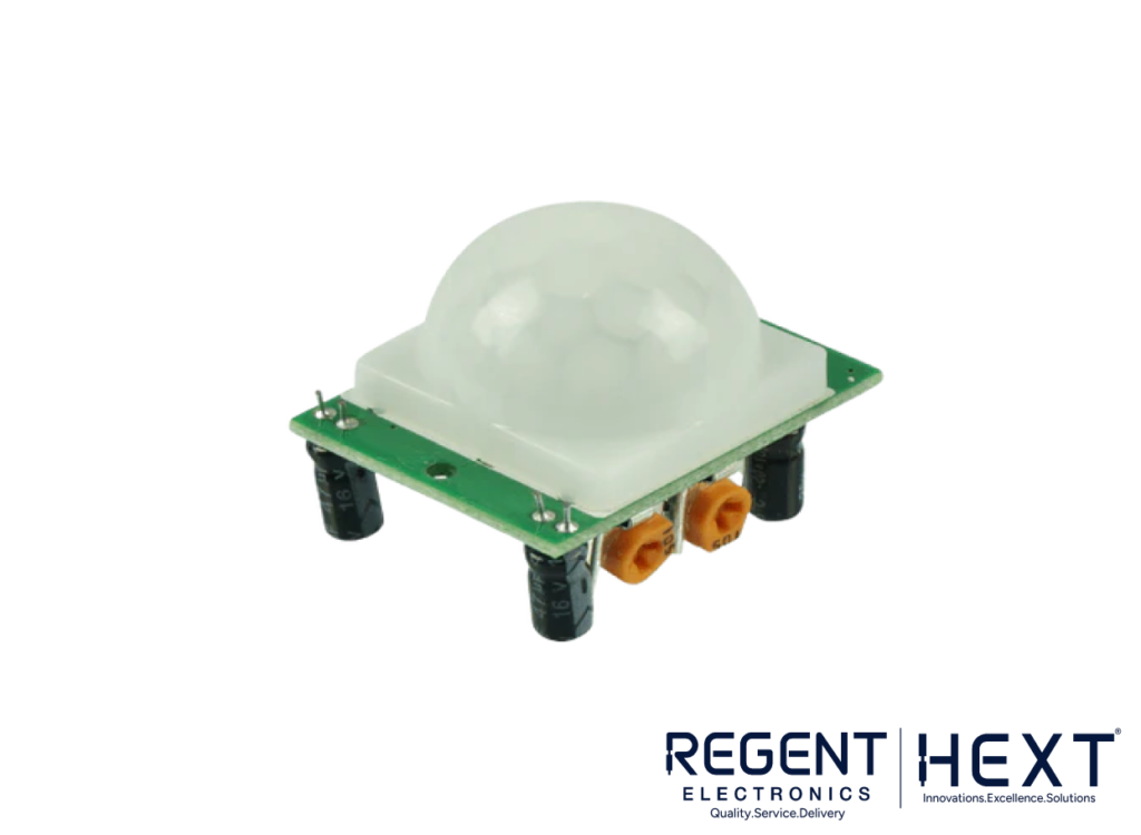
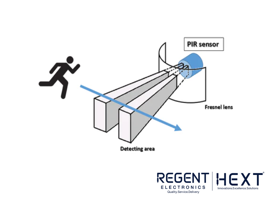
The PIR (Passive Infrared) sensor detects motion based on the infrared radiation emitted by objects in its field of view. Humans and animals emit more infrared radiation due to body heat, which is easily detected by the PIR sensor. When a person or animal moves within the sensor’s detection range, it triggers the sensor to send a signal to the Arduino, activating the alarm.
What is an LM2596 DC-DC Buck Converter?
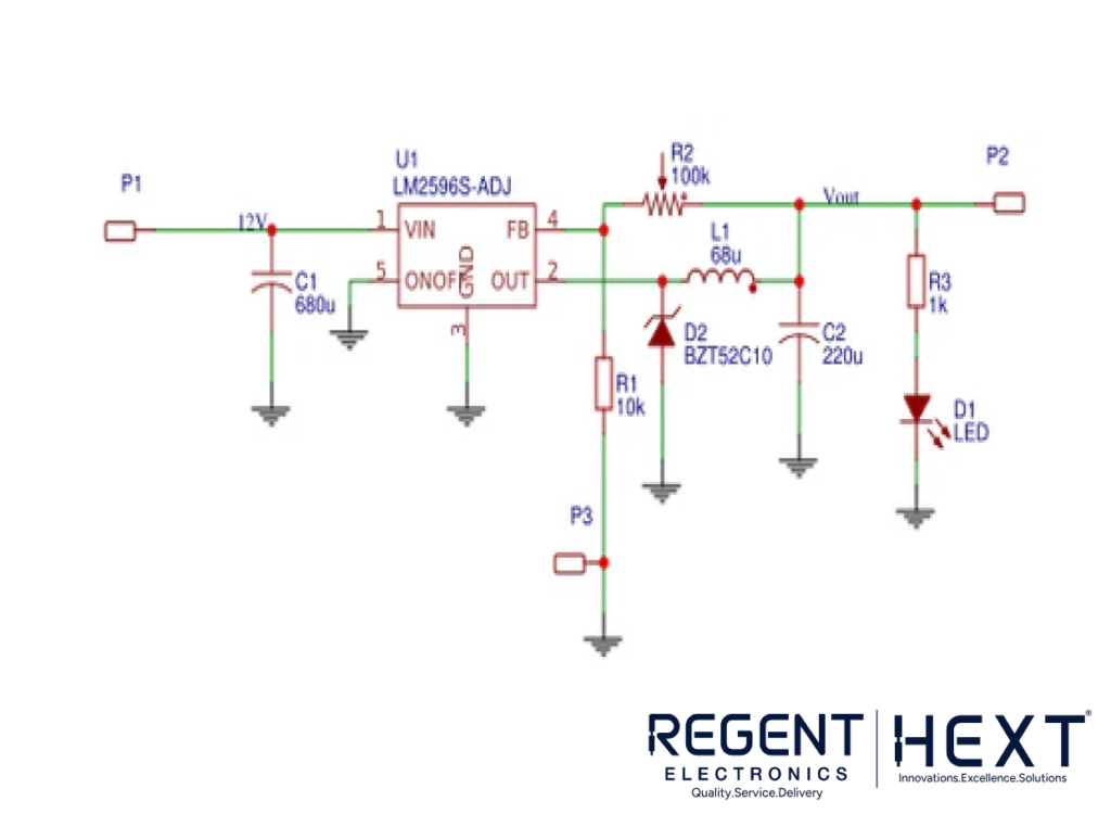
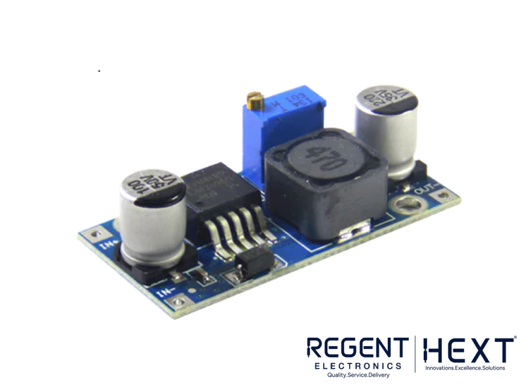
The LM2596 is a highly efficient DC-DC buck converter designed to step down higher input voltages to a lower, stable voltage required by the circuit. It can supply up to 3A of current, which is perfect for powering the SIM800L GSM module. The high efficiency of the LM2596 minimizes heat generation, making it a reliable power source for your burglar alarm system.
Working of the PIR Sensor-Based Burglar Alarm
Here’s how the system works:
- The PIR sensor continuously monitors the area for any motion. If motion is detected, the sensor sends a HIGH signal to the Arduino.
- Upon detecting motion, the Arduino activates the Piezo buzzer, emitting a loud sound to alert you about the intruder.
- The SIM800L GSM module makes an outgoing call to the number stored in the Arduino’s memory, notifying you of the security breach.
- Optionally, you can also add a Reed switch on doors or windows to receive an alert when they are opened.
Circuit Diagram
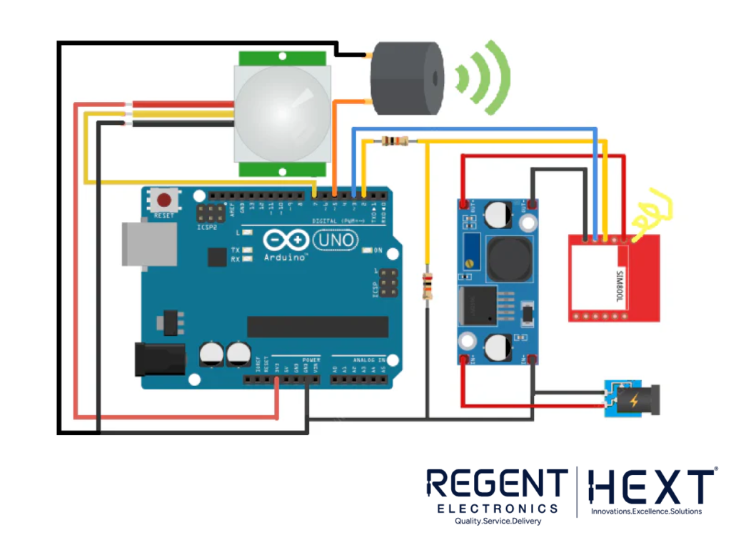
The circuit connects the PIR sensor, SIM800L GSM module, and Piezo buzzer to the Arduino as shown in the diagram. The sensor sends a HIGH signal to the Arduino, which triggers the GSM module to call and the buzzer to sound.
Arduino Code for PIR-Based Burglar Alarm
cpp
CopyEdit
#include <SoftwareSerial.h>
const int PIR = 7; // PIR sensor connected to pin 7
// Create a software serial object to communicate with SIM800L
SoftwareSerial mySerial(3, 2); // SIM800L Tx & Rx are connected to Arduino pins 3 & 2
void setup() {
// Begin serial communication with Arduino and Serial Monitor
Serial.begin(9600);
// Begin serial communication with SIM800L
mySerial.begin(9600);
// Set PIR sensor pin as input
pinMode(PIR, INPUT);
}
void loop() {
// Check if the PIR sensor detects motion
if (digitalRead(PIR) == HIGH) {
// Trigger the buzzer and GSM call
digitalWrite(5, HIGH);
Serial.println(“Motion detected! Calling…”);
// Initiate communication with the SIM800L module
mySerial.println(“AT”); // Check for SIM800L response
delay(1000);
mySerial.println(“ATD+91xxxxxxxxxx;”); // Replace with your phone number
delay(20000); // Wait for 20 seconds to allow the call
mySerial.println(“ATH”); // Hang up the call
}
}
Conclusion
This DIY PIR Sensor-Based Burglar Alarm is a powerful project that combines motion detection and remote notification for enhanced security. By interfacing a PIR sensor, SIM800L GSM module, and Arduino, you can create a cost-effective security system for your home or office. With added features like calling your phone when motion is detected, this alarm system ensures that you’re always informed about any potential security threats.
Start building your own PIR sensor-based burglar alarm today and enjoy the benefits of a smart, connected home security system!