
DIY Pulse Oximeter using MAX30100 Module – A Complete Guide
In this step-by-step guide, you will learn how to build your own Pulse Oximeter using the MAX30100 module and Arduino. This project allows you to measure two critical health parameters: blood oxygen saturation (SpO2) and heart rate (BPM). With an easy-to-use interface, you will display these readings on a 16×2 LCD display. This device is especially useful for people who need to monitor their blood oxygen levels and pulse rate due to conditions like asthma, heart disease, or respiratory issues.
Components Required for Pulse Oximeter:
- Arduino Nano
- MAX30100 Pulse Oximeter Module
- Breadboard
- Connecting Wires
- 10k Potentiometer
- 560 Ohm Resistor
- 16×2 LCD Display
- Power Supply
What is the MAX30100 Pulse Oximeter Module?
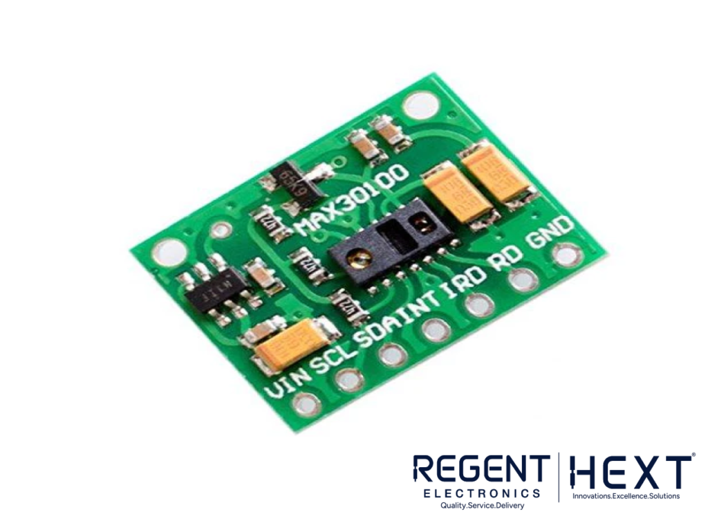
The MAX30100 is a state-of-the-art Pulse Oximeter and heart rate sensor designed for accurate measurement of blood oxygen and pulse rate. This sensor incorporates two types of LEDs: red and infrared (IR). These LEDs emit light through your fingertip, and the photodetector detects how much of the red and infrared light is absorbed. This data helps calculate both SpO2 (blood oxygen concentration) and BPM (beats per minute) accurately.
The MAX30100 module operates in two modes:
- Heart Rate Mode: Only the IR LED is activated.
- Dual Mode: Both the red and IR LEDs are used for detecting both heart rate and oxygen saturation.
This advanced sensor has a built-in FIFO buffer for storing data and provides readings via I2C communication. The module operates on 1.8V to 3.3V and is widely used in wearables, medical monitoring systems, and fitness devices.
How to Interface a 16×2 LCD with Arduino?
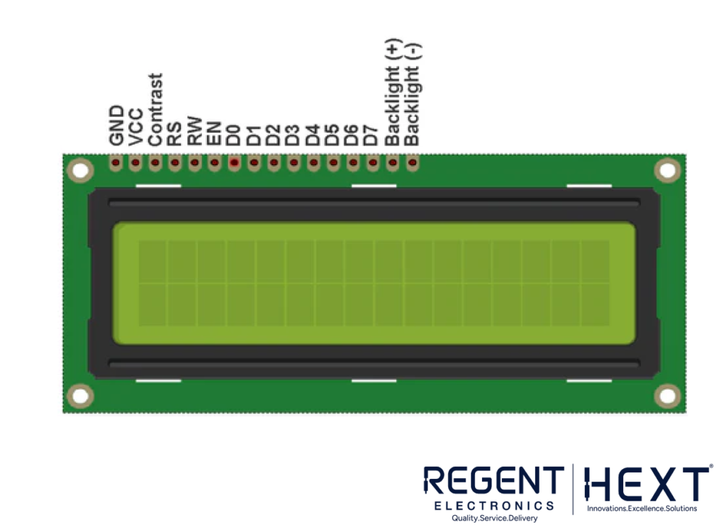
The 16×2 LCD display is an essential component in many embedded systems, and it works seamlessly with Arduino. It is based on the HD44780 driver and has 16 pins, which can be used in 4-bit or 8-bit mode. For this project, we will use the 4-bit mode to reduce the number of connections.
Pin Configuration:
- Vss (Pin 1): Ground pin for LCD.
- Vcc (Pin 2): 5V power supply for the LCD.
- VEE (Pin 3): Contrast adjustment pin connected to a 10k potentiometer.
- RS (Pin 4): Register select pin (selects command or data).
- RW (Pin 5): Read/Write mode pin.
- E (Pin 6): Enable pin to trigger data transfer.
- DB0 to DB7 (Pins 7-14): Data pins used to send commands or data.
- Backlight + (Pin 15): Anode pin for backlight.
- Backlight – (Pin 16): Cathode pin for backlight.
How Does the MAX30100 Module Work?
The MAX30100 uses red and infrared LEDs to emit light through the fingertip. Oxygenated blood absorbs more infrared light and allows more red light to pass through, while deoxygenated blood absorbs more red light and allows more infrared light to pass through. The sensor uses this principle to calculate SpO2 and heart rate by measuring the variations in light absorption.
The MAX30100 sensor collects this data and processes it with low-noise signal processing, storing it in a FIFO buffer. It then sends the data to the Arduino via the I2C communication protocol. The heart rate is detected by measuring the changes in blood volume as the heart beats, while the SpO2 is derived from the difference in light absorption between oxygenated and deoxygenated blood.
Circuit Diagram for Pulse Oximeter with MAX30100
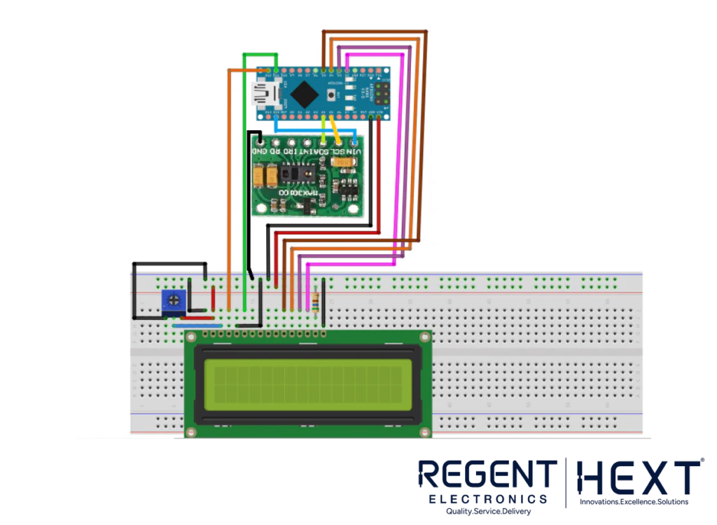
The circuit connects the MAX30100 module to the Arduino Nano and 16×2 LCD display as shown in the diagram. Once the system is powered up, you can place your finger on the MAX30100 sensor, and it will start displaying the heart rate and blood oxygen levels on the LCD screen.
Arduino Code for MAX30100 Pulse Oximeter
cpp
CopyEdit
#include <LiquidCrystal.h>
#include <Wire.h>
#include “MAX30100_PulseOximeter.h”
LiquidCrystal lcd(12, 11, 5, 4, 3, 2);
#define REPORTING_PERIOD_MS 1000
PulseOximeter pox;
uint32_t tsLastReport = 0;
void onBeatDetected() {
Serial.println(“Beat!”);
}
void setup() {
Serial.begin(115200);
Serial.print(“Initializing pulse oximeter..”);
lcd.begin(16, 2);
lcd.print(“Initializing…”);
delay(3000);
lcd.clear();
if (!pox.begin()) {
Serial.println(“FAILED”);
for(;;);
} else {
Serial.println(“SUCCESS”);
}
pox.setIRLedCurrent(MAX30100_LED_CURR_7_6MA);
pox.setOnBeatDetectedCallback(onBeatDetected);
}
void loop() {
pox.update();
if (millis() – tsLastReport > REPORTING_PERIOD_MS) {
Serial.print(“Heart rate: “);
Serial.print(pox.getHeartRate());
Serial.print(“bpm / SpO2: “);
Serial.print(pox.getSpO2());
Serial.println(“%”);
lcd.clear();
lcd.setCursor(0, 0);
lcd.print(“BPM: “);
lcd.print(pox.getHeartRate());
lcd.setCursor(0, 1);
lcd.print(“SpO2: “);
lcd.print(pox.getSpO2());
lcd.print(“%”);
tsLastReport = millis();
}
}
Conclusion
Building your own pulse oximeter with the MAX30100 module and Arduino is a fun and educational project that results in a highly useful device for monitoring blood oxygen levels and heart rate. By integrating a 16×2 LCD display, this DIY project provides an easy way to visualize the measurements in real-time, making it an essential tool for individuals with respiratory or cardiovascular concerns.
Start building your own Arduino-based pulse oximeter today, and enjoy the benefits of tracking your vital health parameters with accuracy!