
DIY RFID-Based Door Lock: A Step-by-Step Guide
Welcome to our innovative DIY guide on creating an RFID-based door lock system using Arduino! In this tutorial, you’ll learn how to design and implement an RFID-based solenoid door lock. We’ll walk you through the process of interfacing an Arduino board with an RFID MF-RC522 module to control a solenoid lock. This project is perfect for anyone looking to add secure and convenient access control, similar to the systems used in hotels, metro stations, or gym lockers.
Components Required:
- Arduino Board (e.g., Arduino Uno)
- 16×2 LCD Display
- RC522 RFID Module (with RFID Tag and Card)
- Buzzer
- 10k Potentiometer
- 560-ohm Resistor
- Electromagnetic Solenoid Lock
- Connecting Wires
- Power Supply
- BC547 Transistor
- 1N4007 Diode
- Breadboard
Understanding the RC522 RFID Module:
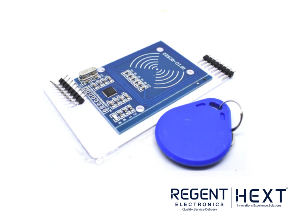
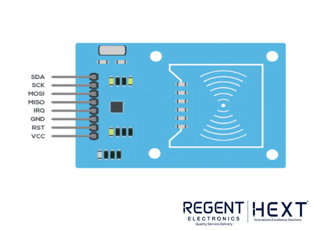
The RC522 is a popular 13.56 MHz RFID reader module based on the MFRC522 controller from NXP Semiconductors. It supports several communication protocols including SPI, I2C, and UART, making it highly flexible for different projects. The module is used with RFID cards or tags that contain 1KB of memory.
RFID technology consists of three main components: the scanning antenna, the transceiver, and the transponder (the RFID tag). The reader transmits a signal to the RFID tag, which responds with data. RFID tags can either be passive (powered by the reader) or active (powered by an internal battery).
How to Interface a 16×2 LCD with Arduino:
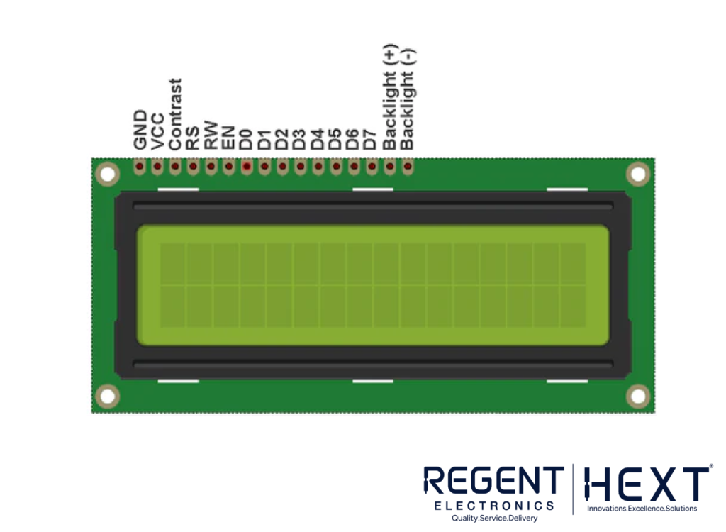
The 16×2 LCD module is an essential component in many Arduino-based projects. In this guide, we’ll be using the JHD162A LCD, which works with the HD44780 controller. It can be connected in 4-bit or 8-bit mode, but for this project, we’ll be using the 4-bit mode.
The key connections for the LCD module are:
- VSS (Pin 1): Ground
- VCC (Pin 2): Power (+5V)
- VEE (Pin 3): Contrast control (via a 10k potentiometer)
- RS, RW, EN: Control pins for selecting data or command mode
- DB0-DB7: Data pins for sending data/commands
- Backlight pins: Used to power the backlight LED
How Does a Solenoid Lock Work?
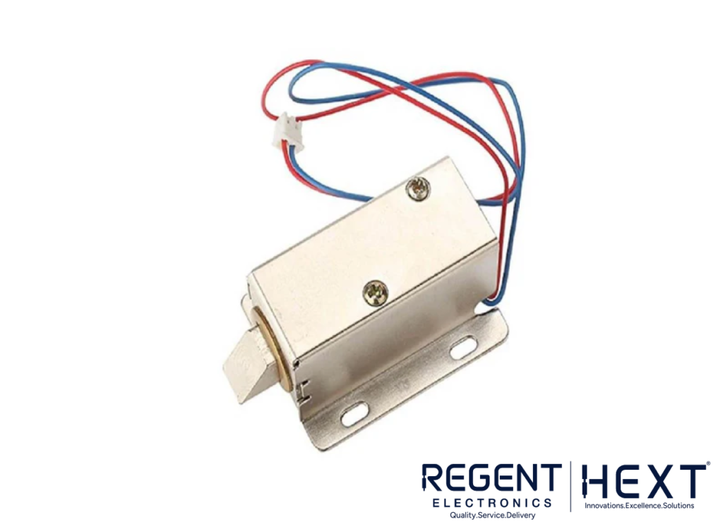
A solenoid lock consists of an electromagnet that, when powered, moves a plunger to either lock or unlock the door. The electromagnetic solenoid acts as the locking mechanism, which can be triggered by the Arduino board in response to the RFID tag authentication.
Working Principle of the RFID Door Lock System:
- Master Card Setup: Initially, you need to set up a master card. This card allows the addition and removal of RFID cards from the system.
- Card Authentication: When an authorized RFID tag is swiped over the reader, the door unlocks. Unauthorized tags trigger an access denied message on the LCD and activate the buzzer.
- Programming Mode: The master card allows you to enter the programming mode to manage the list of authorized cards.
Arduino Code:
cpp
CopyEdit
#include <EEPROM.h>
#include <SPI.h>
#include <MFRC522.h>
#include <LiquidCrystal.h>
int Relay = A5;
boolean match = false;
boolean programMode = false;
int successRead;
byte storedCard[4];
byte readCard[4];
byte masterCard[4];
#define SS_PIN 10
#define RST_PIN 9
MFRC522 mfrc522(SS_PIN, RST_PIN);
LiquidCrystal lcd(7, 6, 5, 4, 3, 2);
void setup() {
Serial.begin(9600);
lcd.begin(16, 2);
pinMode(8, OUTPUT);
pinMode(Relay, OUTPUT);
SPI.begin();
mfrc522.PCD_Init();
mfrc522.PCD_SetAntennaGain(mfrc522.RxGain_max);
if (EEPROM.read(1) != 1) {
lcd.setCursor(0, 0);
lcd.println(“Set Master Card”);
lcd.setCursor(0, 1);
lcd.println(“Scan a card…”);
delay(1500);
do {
successRead = getID();
} while (!successRead);
for (int j = 0; j < 4; j++) {
EEPROM.write(2 + j, readCard[j]);
}
EEPROM.write(1, 1);
}
// More setup code…
}
How to Set Up the System:
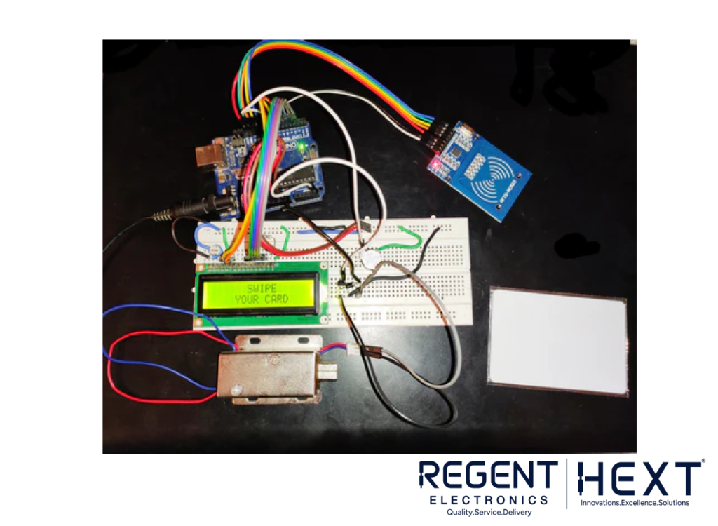
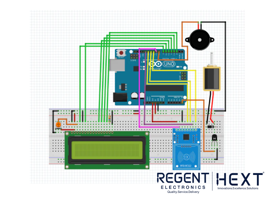
- Connect the Components: Wire the Arduino, RFID module, LCD, and solenoid lock following the circuit diagram.
- Upload the Code: Upload the Arduino code to your board. This will enable the system to read RFID tags, display information on the LCD, and control the solenoid lock.
Final Thoughts:
This RFID-based door lock system is an excellent way to add security to your home, office, or any other space requiring controlled access. The integration of Arduino with RFID technology and solenoid locks provides an easy, efficient, and customizable solution for automated access control.
For more projects like this, check out our range of Arduino components and modules at Regent Electronics. Whether you’re a beginner or an expert, we offer everything you need to bring your DIY ideas to life!