
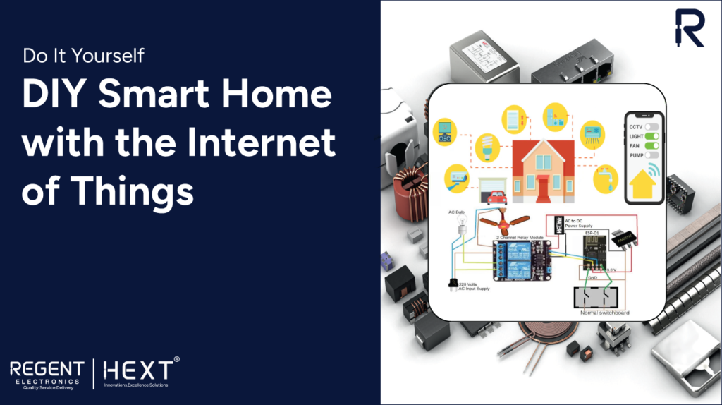
Create Your Own Smart Home Automation System with Blynk App and ESP8266
Introduction to DIY Smart Home Automation with IoT
In recent years, smart homes powered by the Internet of Things (IoT) have become increasingly popular. With IoT, homeowners can control their appliances, lighting, fans, and other devices from anywhere in the world using mobile applications. In this guide, we’ll walk you through how to build a low-cost, Google Assistant-integrated smart home appliance control system using the ESP8266 WiFi module (ESP-01) or NodeMCU, along with the Blynk app.
Whether you want to build this system for personal use or as a product for resale, this tutorial will show you how to set up a Wi-Fi-enabled device to control household items such as lights, fans, and more from your Android phone. You’ll also be able to monitor the live status of your devices, giving you complete control over your smart home.
Required Components
- ESP8266 WiFi module (ESP-01) / NodeMCU
- 5V Relay Module
- Connecting Wires
- 230V AC to 5V DC Power Supply (HLK-PM01)
- LM1117 / AMS1117 3.3V Regulator
- AC Appliances (e.g., Fan, Light)
- Wi-Fi Router
- Electrical Tape
- Arduino Board / FTDI Programmer
Understanding the ESP8266 WiFi Module (ESP-01) / NodeMCU
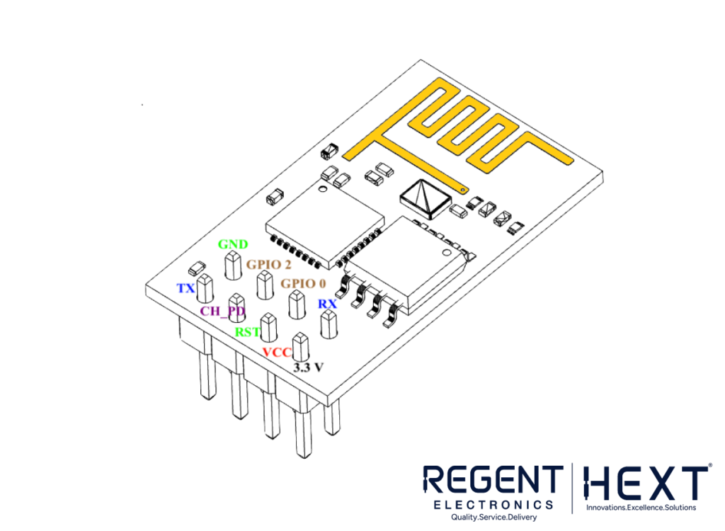
The ESP8266 ESP-01 is a compact Wi-Fi module, enabling microcontrollers to connect to a Wi-Fi network. This self-contained System on a Chip (SoC) eliminates the need for additional microcontrollers like Arduino. It’s perfect for building Wi-Fi-enabled devices without adding extra complexity.
Here’s a quick overview of the pin configuration:
- VCC: 3.3V DC Power Input
- GND: Ground Pin
- TXD: UART Transmitter Pin (GPIO 1)
- RXD: UART Receiver Pin (GPIO 3)
- RESET: Active LOW Reset Pin
- CH_PD: Active HIGH Chip Enable Pin
- GPIO0: Used to enable programming mode or for I/O functions
- GPIO2: General Purpose I/O Pin
If you’re not using the ESP-01 module, you can skip ahead to NodeMCU-specific sections.
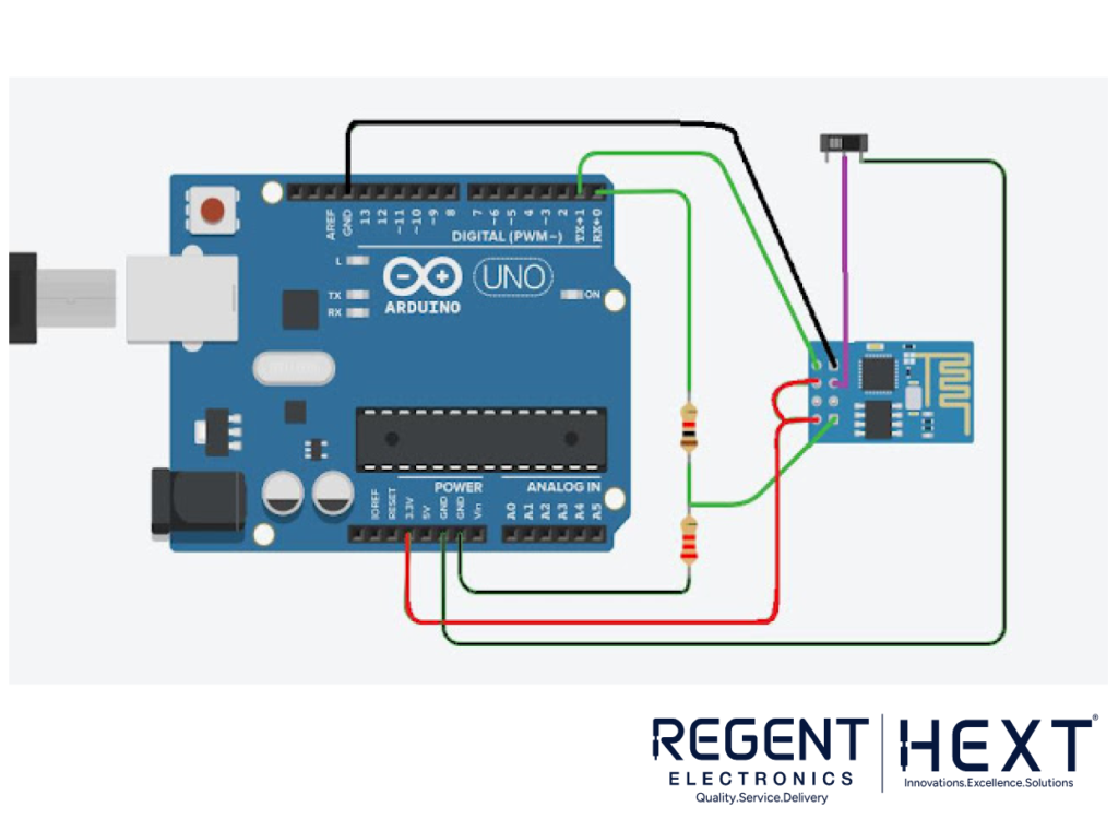
Circuit Setup with Arduino for Uploading Sketch
To program the ESP8266 module, connect it to an Arduino board, ensuring proper communication between the pins (Rx to Rx, Tx to Tx). Remember, the ESP8266 operates on 3.3V, so use a voltage divider for safe transmission from the Arduino.
NodeMCU Overview
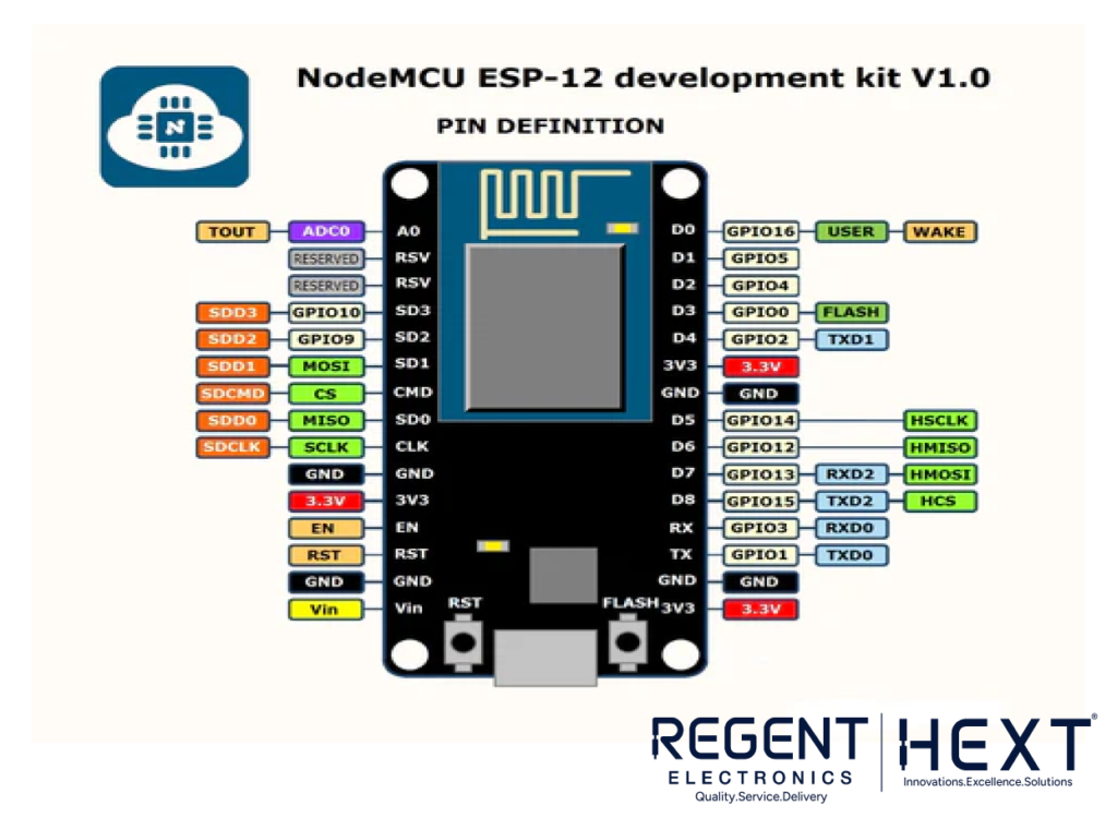
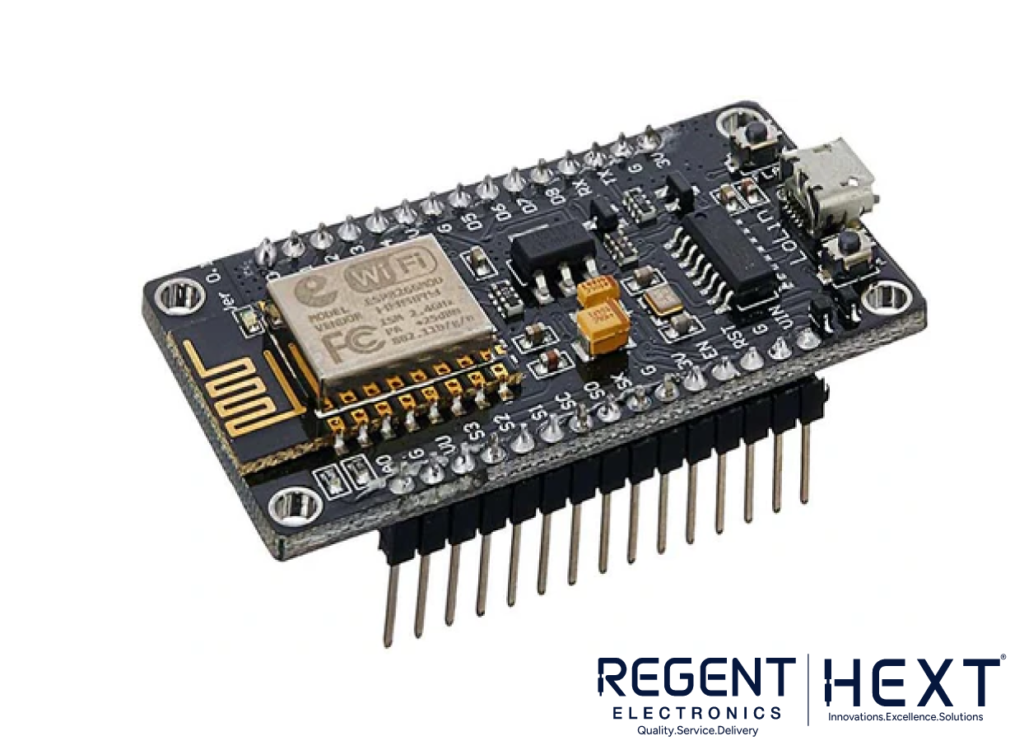
The NodeMCU is a popular ESP8266-based microcontroller that integrates a Wi-Fi chip and a PCB antenna. It features 17 GPIO pins, but be cautious as GPIO6 to GPIO11 are often reserved for the flash chip. Additionally, NodeMCU supports PWM, IIC, and SPI communication, and is ideal for IoT applications like web servers and data fetching.
Programming NodeMCU with Arduino IDE
To program your NodeMCU, follow these steps:
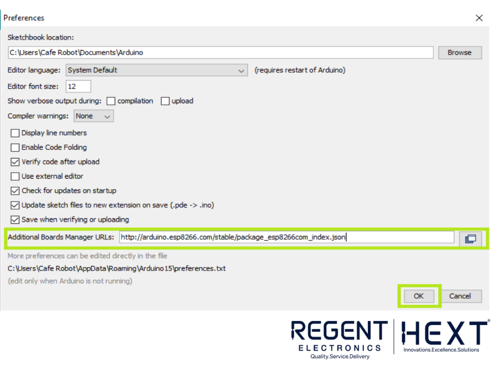
- Install ESP8266 Board: In the Arduino IDE, navigate to File > Preferences, and in the “Additional Boards Manager URLs,” add this URL: http://arduino.esp8266.com/stable/package_esp8266com_index.json
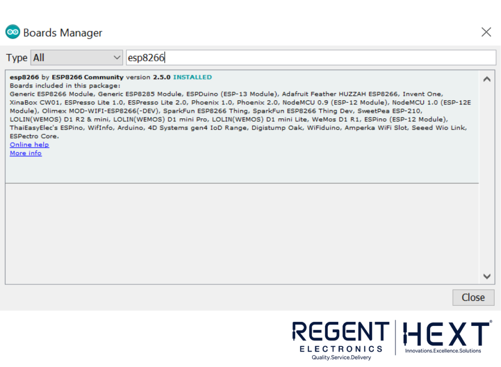
- Install the Board: Go to Tools > Board > Boards Manager, search for “ESP8266,” and install the package.
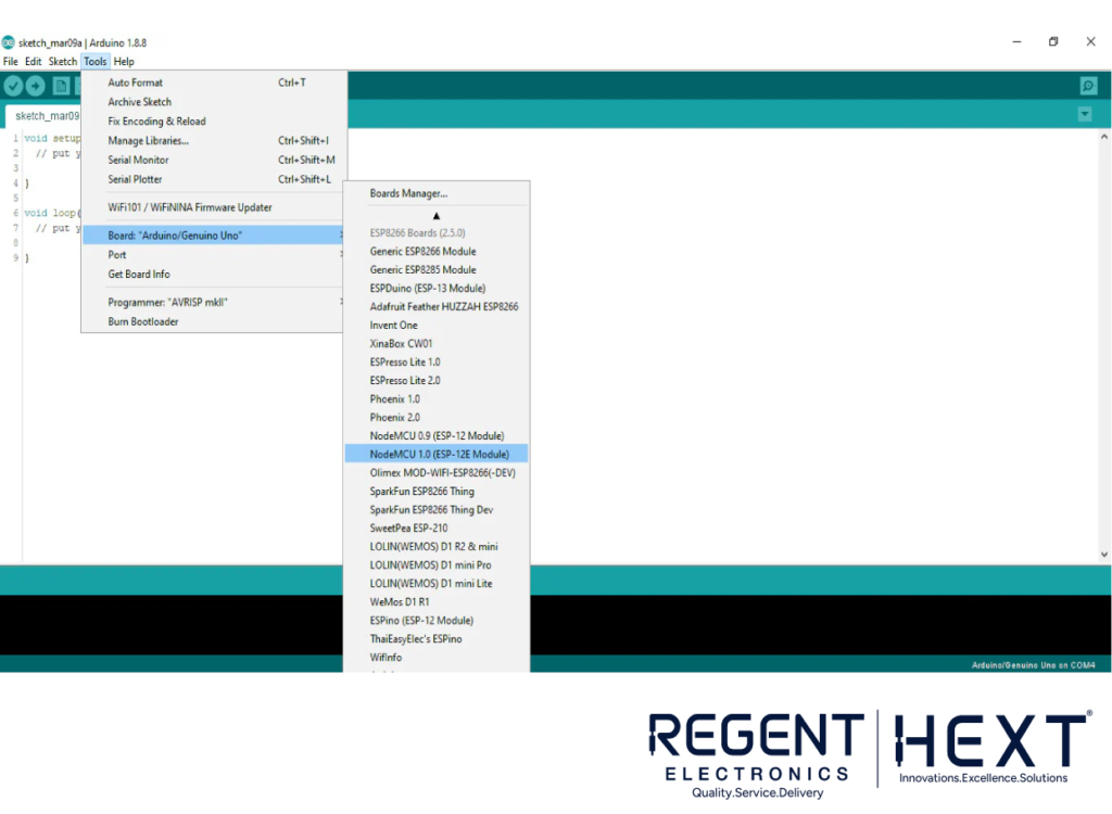
Now, you can select your NodeMCU board in the IDE, and start coding!
Setting up the Blynk App for IoT Control
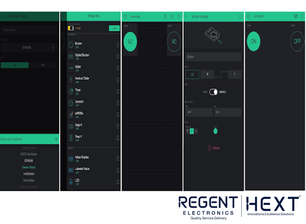
Blynk is a powerful platform that allows you to control your IoT devices remotely via a mobile app. Here’s how to set it up:
- Install the Blynk App: Download the Blynk app on your smartphone (available for both iOS and Android).
- Create a New Project: In the app, create a new project and select NodeMCU as the hardware device.
- Drag and Drop Widgets: Add buttons from the widget section to control devices. Assign virtual pins V0 and V2 to the buttons.
- Set Up Authentication Key: In the app settings, you’ll receive an authentication key. Copy this key into your code to enable communication between your NodeMCU and the app.
Integrating with Google Assistant via IFTTT

To control your devices using Google Assistant, we’ll integrate the system with IFTTT:

- Sign Up for IFTTT: Create an IFTTT account using your Google or Facebook credentials.
- Create a New Applet: After signing in, click on “Create,” then “This” to choose Google Assistant.
- Set Commands: Choose “Say a simple phrase,” and define phrases like “Turn on the light” or “Switch on the fan.” Set a custom reply for Google Assistant, such as “Okay, turning on the light.”
- Link to Webhooks: Select the “That” section, and choose Webhooks. Use the URL format: http://188.166.206.43/YourAuthTokenHere/update/DigitalPinHere


Use GPIO pins V2 and V0 for controlling the relay. Create separate applets for turning devices on and off.
Circuit Diagram
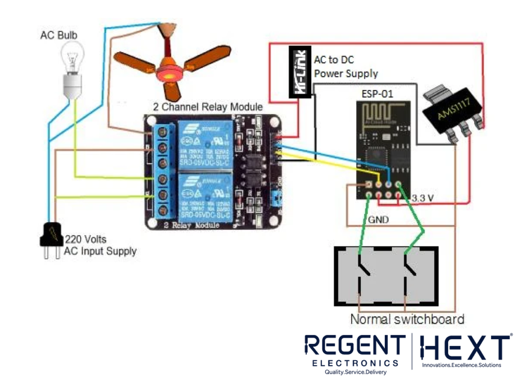
The connection diagram for the system remains the same whether you’re using ESP-01 or NodeMCU. With NodeMCU’s additional pins, you can control more appliances. Ensure all connections are secure to avoid any faults. For better aesthetics, consider designing your own PCB.
Arduino Code for Blynk Integration
cpp
CopyEdit
#define BLYNK_PRINT Serial
#define RELAY_PIN_1 2
#define PUSH_BUTTON_1 1
#define VPIN_BUTTON_1 V2
#define RELAY_PIN_2 0
#define PUSH_BUTTON_2 3
#define VPIN_BUTTON_2 V0
#include <ESP8266WiFi.h>
#include <BlynkSimpleEsp8266.h>
char auth[] = “YourAuthKey”;
char ssid[] = “YourSSID”;
char pass[] = “YourPassword”;
BlynkTimer timer;
int relay1State = LOW;
int relay2State = LOW;
int pushButton1State = HIGH;
int pushButton2State = HIGH;
void setup() {
Serial.begin(9600);
Blynk.begin(auth, ssid, pass);
pinMode(RELAY_PIN_1, OUTPUT);
pinMode(PUSH_BUTTON_1, INPUT_PULLUP);
pinMode(RELAY_PIN_2, OUTPUT);
pinMode(PUSH_BUTTON_2, INPUT_PULLUP);
timer.setInterval(500L, checkPhysicalButton);
}
void loop() {
Blynk.run();
timer.run();
}
void checkPhysicalButton() {
if (digitalRead(PUSH_BUTTON_1) == LOW) {
if (pushButton1State != LOW) {
relay1State = !relay1State;
digitalWrite(RELAY_PIN_1, relay1State);
Blynk.virtualWrite(VPIN_BUTTON_1, relay1State);
}
pushButton1State = LOW;
} else {
if (pushButton1State != HIGH) {
relay1State = !relay1State;
digitalWrite(RELAY_PIN_1, relay1State);
Blynk.virtualWrite(VPIN_BUTTON_1, relay1State);
}
pushButton1State = HIGH;
}
if (digitalRead(PUSH_BUTTON_2) == LOW) {
if (pushButton2State != LOW) {
relay2State = !relay2State;
digitalWrite(RELAY_PIN_2, relay2State);
Blynk.virtualWrite(VPIN_BUTTON_2, relay2State);
}
pushButton2State = LOW;
} else {
if (pushButton2State != HIGH) {
relay2State = !relay2State;
digitalWrite(RELAY_PIN_2, relay2State);
Blynk.virtualWrite(VPIN_BUTTON_2, relay2State);
}
pushButton2State = HIGH;
}
}
Conclusion
By following these steps, you can build a fully functional smart home automation system using Blynk and the ESP8266 WiFi module (ESP-01) or NodeMCU. With integration to Google Assistant, you’ll be able to control your devices hands-free using voice commands. This project is a great way to dive into the world of IoT, providing both a learning experience and a practical home automation solution.
Make Your Home Smarter Today with Regent Electronics