
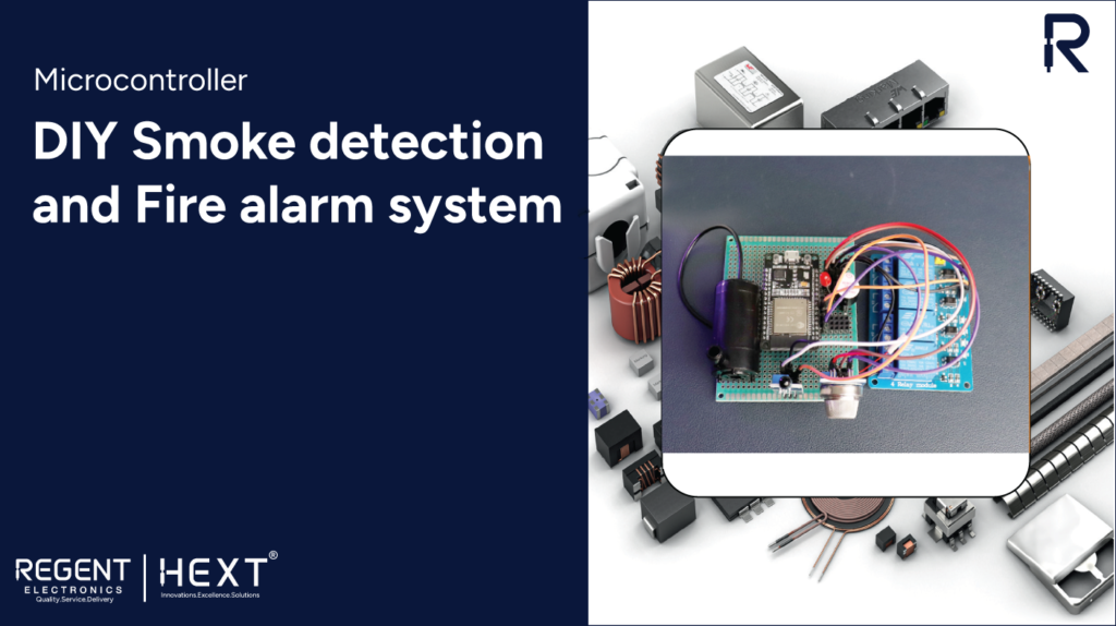
How to Build an Advanced Smoke Detection and Fire Alarm System Using MQ-135 Gas Sensor, Flame Sensor, and ESP32
Are you looking for an efficient DIY smoke detection and fire alarm system? This guide will help you create an IoT-based fire alarm system using an ESP32, MQ-135 gas detector, and a flame sensor. Integrated with the Arduino IoT Cloud, this system allows for remote monitoring and enhances safety measures.
Introduction
Fires and gas leaks pose serious risks to life and property. A robust fire detection system can help prevent these hazards by providing early warnings. In this project, we will integrate an ESP32 with the MQ-135 gas sensor and a flame sensor to develop a real-time smoke detection and fire alarm system. The system is connected to the Arduino IoT Cloud for remote monitoring.
Components Required
Hardware Requirements:
- ESP32 board
- MQ-135 Gas Detector Sensor
- Flame Sensor
- Buzzer
- LED
- Relay Module
- Water Pump
- USB Data Cable
- Jumper Wires
- Universal PCB
- Breadboard
Software Requirements:
- Arduino IDE
- Arduino Cloud Web
- Arduino IoT Remote App
- Arduino Create Agent
Understanding the Components
MQ-135 Gas Sensor
The MQ-135 sensor is an air quality and gas detection sensor capable of detecting ammonia, sulfide, benzene, and other toxic gases. It has a low conductivity in clean air and increases conductivity when exposed to combustible gases, producing an output signal corresponding to the gas concentration.
MQ-135 Features:
- Detects harmful gases and air pollution
- 4 pins: VCC, GND, A0, D0
- Operating voltage: 2.5V – 5V
- Suitable for industrial pollution monitoring, toxic gas detection, and air quality control
Flame Sensor
A flame sensor is essentially an IR detector that can sense flames and light sources within the 760nm~1100nm wavelength range at distances of up to 80cm. The sensor’s sensitivity can be adjusted using a potentiometer.
Flame Sensor Features:
- Detects fire and flames
- Produces digital output at D0
- Can be used in fire alarm and automatic fire suppression systems
Setting Up the Arduino IoT Cloud
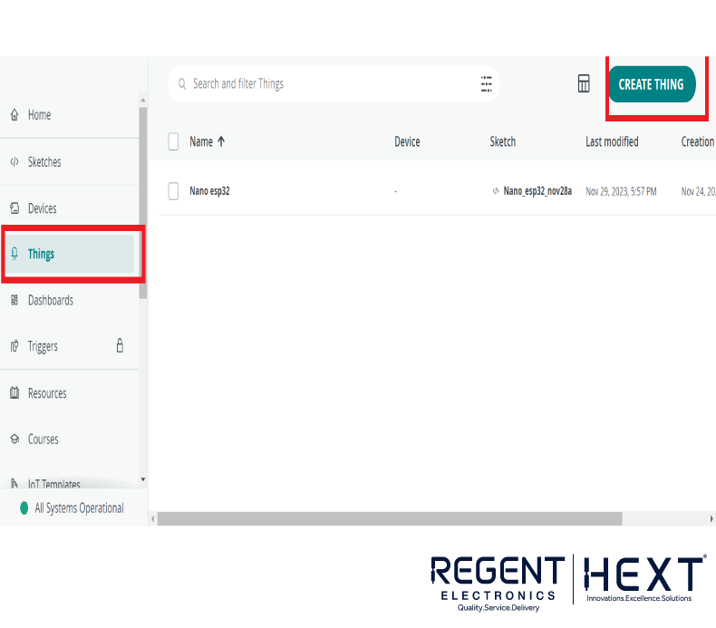
- Create an Arduino Cloud Account
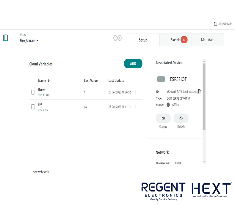
- Go to “Things” > Click on “Create Thing”
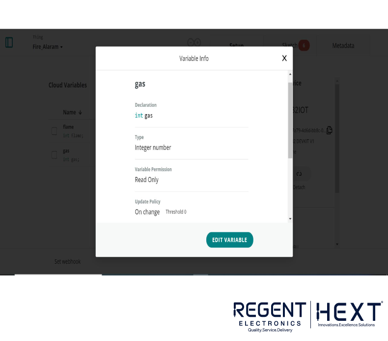
- Add Variables:
- Variable 1: Name – gas, Type – Integer, Permission – Read Only, Update Policy – On Change
- Variable 2: Name – flame, Type – Integer, Permission – Read Only, Update Policy – On Change
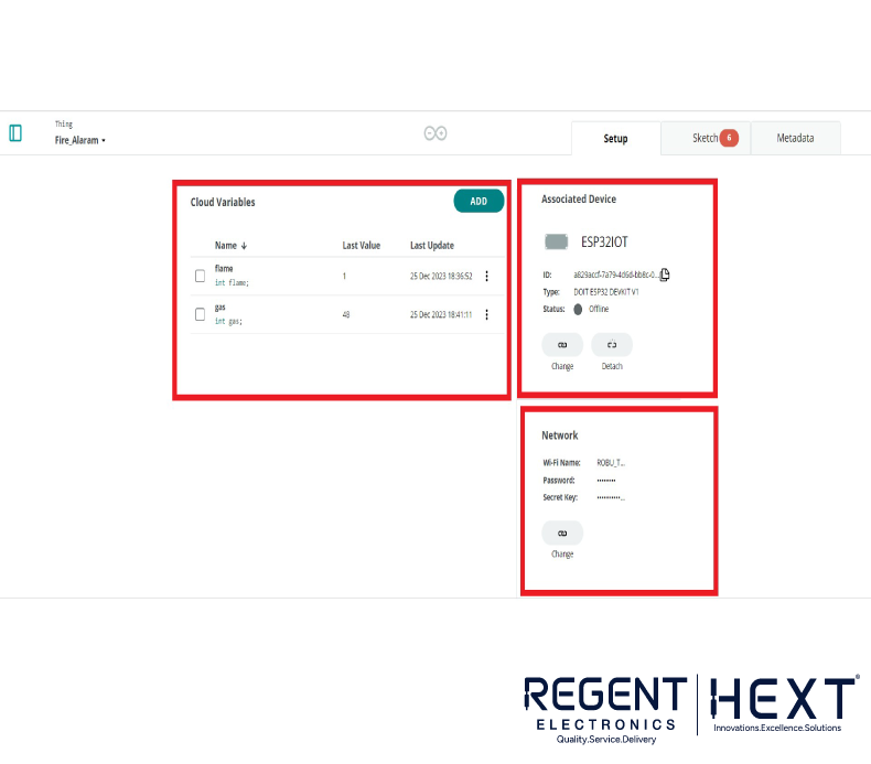
- Select the Device
- Choose DOIT ESP32 DEVKIT V1
- Save the Device ID and Device Secret Key
- Configure Network
- Enter Wi-Fi Name, Wi-Fi Password, and Device Secret Key
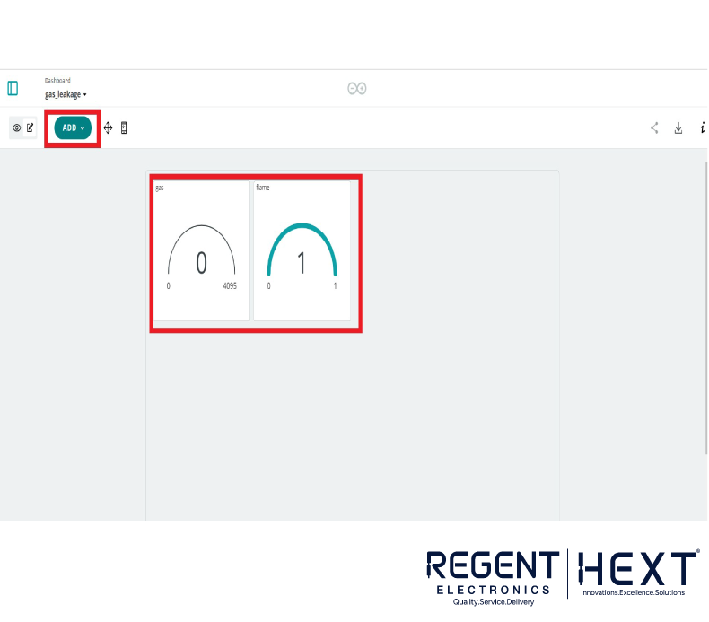
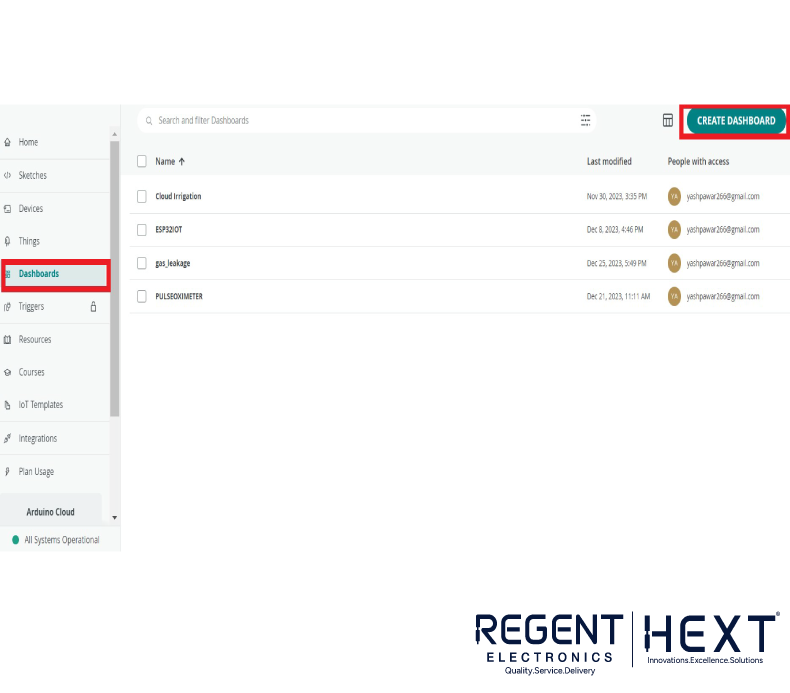
- Create a Dashboard
- Add widgets (gauges) for “Gas” and “Flame” values
- Link them to the respective variables
Circuit Diagram and Wiring
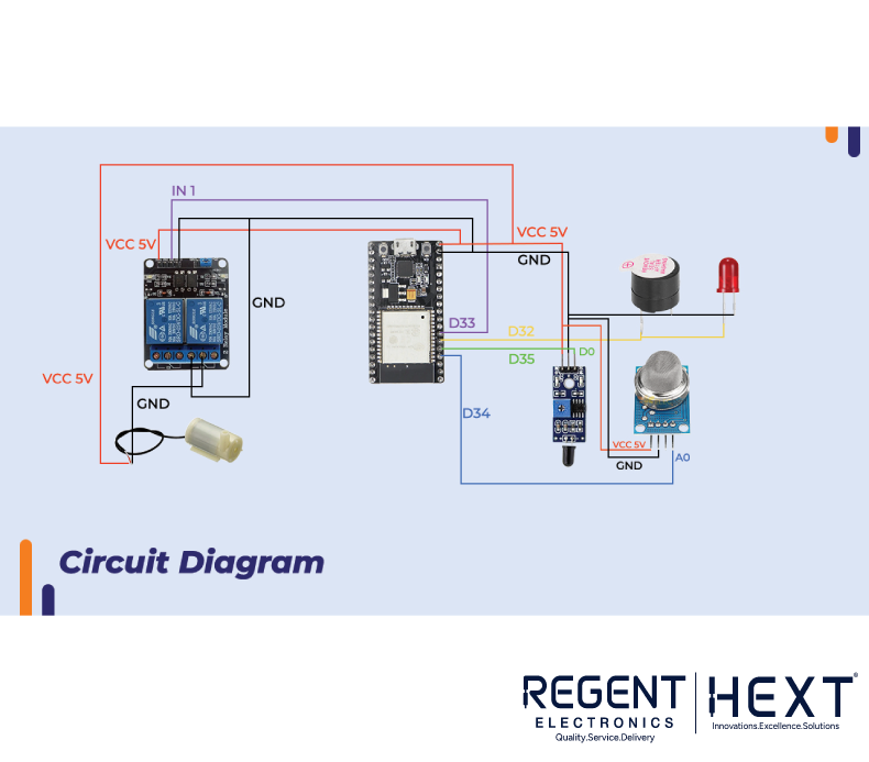
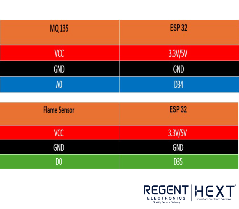
- MQ-135: Connect VCC to 3.3V, GND to GND, A0 to D34
- Flame Sensor: Connect VCC to 3.3V, GND to GND, D0 to D35
- Relay Module: Connect IN to D33, VCC to 3.3V, GND to GND
- Buzzer & LED: Connect to D32
- Water Pump: Connected through the Relay Module
Uploading the Code
Libraries Required
Ensure you have the following libraries installed in Arduino IDE:
- ArduinoIoTCloud.h
- Arduino_ConnectionHandler.h
Code Implementation
#include “arduino_secrets.h”
#include “thingProperties.h”
int gas_data = 34;
int flame_data = 35;
int Alarm = 32;
int relay = 33;
void setup() {
Serial.begin(9600);
delay(1500);
pinMode(gas_data, INPUT);
pinMode(flame_data, INPUT);
pinMode(Alarm, OUTPUT);
pinMode(relay, OUTPUT);
initProperties();
ArduinoCloud.begin(ArduinoIoTPreferredConnection);
setDebugMessageLevel(2);
ArduinoCloud.printDebugInfo();
}
void loop() {
ArduinoCloud.update();
gas = analogRead(gas_data);
flame = digitalRead(flame_data);
if (gas > 200) {
digitalWrite(Alarm, HIGH);
delay(5000);
} else if (flame < 1) {
digitalWrite(relay, HIGH);
delay(5000);
digitalWrite(relay, LOW);
} else {
digitalWrite(Alarm, LOW);
digitalWrite(relay, LOW);
}
}
Cloud Integration
thingProperties.h
#include <ArduinoIoTCloud.h>
#include <Arduino_ConnectionHandler.h>
const char DEVICE_LOGIN_NAME[] = “”;
const char SSID[] = SECRET_SSID;
const char PASS[] = SECRET_OPTIONAL_PASS;
const char DEVICE_KEY[] = SECRET_DEVICE_KEY;
void onFlameChange();
void onGasChange();
int flame;
int gas;
void initProperties() {
ArduinoCloud.setBoardId(DEVICE_LOGIN_NAME);
ArduinoCloud.setSecretDeviceKey(DEVICE_KEY);
ArduinoCloud.addProperty(flame, READWRITE, ON_CHANGE, onFlameChange);
ArduinoCloud.addProperty(gas, READWRITE, ON_CHANGE, onGasChange);
}
WiFiConnectionHandler ArduinoIoTPreferredConnection(SSID, PASS);
Final Testing & Working
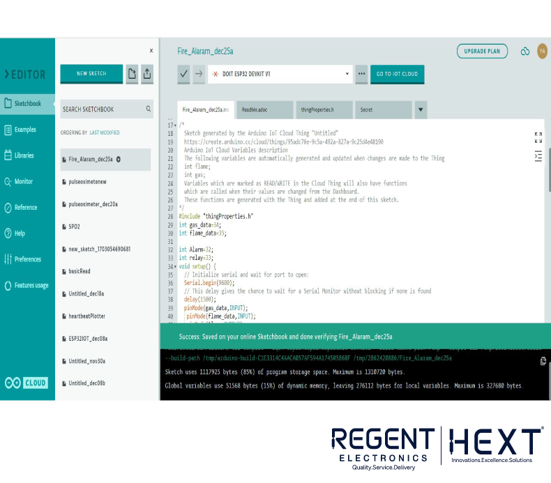
Once all connections are made:
- Upload the code to ESP32.
- Monitor the real-time gas and flame data on Arduino Cloud.
- If gas levels exceed 200 or a flame is detected, the relay activates, turning on the water pump and alarm system.
Conclusion
This IoT-based smoke detection and fire alarm system enhances fire safety by providing real-time monitoring and alerts. The system can be implemented in homes, industries, and workplaces to prevent fire hazards effectively. By integrating Arduino Cloud, remote monitoring is made seamless and efficient.
Start building your smart fire alarm system today and ensure safety for your surroundings!