

Interfacing LDR Sensor with Arduino – Step-by-Step Guide with Code
Introduction
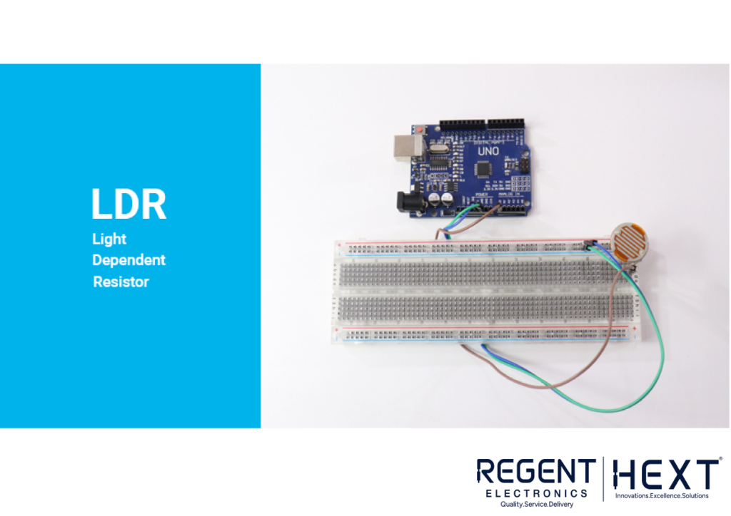
A Light Dependent Resistor (LDR) is a sensor that changes its resistance based on light intensity. In this guide, we will discuss what an LDR sensor is, its working principle, and how to interface it with an Arduino board.
What is an LDR Sensor?
An LDR, also known as a photoresistor, is a light-sensitive device whose resistance decreases as the intensity of light increases. It is widely used in applications like automatic street lights, alarms, and electronic devices that require light-based detection.
Applications of LDR Sensors:
- Streetlights and stud lights – Turn on/off based on ambient light.
- Alarm systems – Detect changes in light levels for security purposes.
- Home automation – Automate lights and electronic devices based on light availability.
Components Required
- LDR Sensor
- Arduino Uno
- Relay Module (for LED control)
- Breadboard
- Jumper Wires
How LDR Sensors Work
The LDR sensor is made of a photosensitive material, usually cadmium sulfide, which changes its resistance based on light intensity. When light falls on the material, its resistance decreases, allowing current to pass through. Conversely, in darkness, resistance increases, restricting current flow.
Interfacing LDR with Arduino

To use an LDR sensor with Arduino, follow these connection steps:
Connections
- Connect one terminal of the LDR sensor to analog pin A0 on Arduino.
- Connect the same terminal to the 5V pin on Arduino via a 10KΩ pull-down resistor.
- Connect the other terminal of the LDR sensor to the GND pin on Arduino.
Arduino Code for LDR Sensor
const int ledPin = 13;
const int ldrPin = A0;
void setup() {
Serial.begin(9600);
pinMode(ledPin, OUTPUT);
pinMode(ldrPin, INPUT);
}
void loop() {
int ldrValue = analogRead(ldrPin);
if (ldrValue <= 200) {
digitalWrite(ledPin, HIGH);
Serial.print(“It’s Night Time, Turn on the LED: “);
} else {
digitalWrite(ledPin, LOW);
Serial.print(“It’s Day Time, Turn off the LED: “);
}
Serial.println(ldrValue);
delay(500);
}
Explanation
- The analogRead() function reads the LDR sensor value.
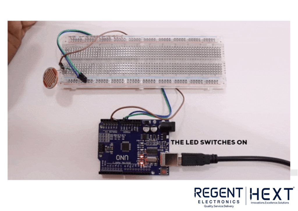
- If the value is below 200, the LED turns ON (indicating night time).
- If the value is above 200, the LED turns OFF (indicating daytime).
- The readings are printed to the Serial Monitor for debugging.
How to Control an LED Bulb with LDR and Relay Module
If you want to control a high-power LED bulb using the LDR sensor, follow these additional steps:
Steps:
- Connect the relay module:
- IN pin → Digital pin D7 on Arduino
- VCC → 5V
- GND → GND
- Connect the high-power LED bulb to the relay module’s output terminals.
Updated Code for Relay Control
const int relayPin = 7;
const int ldrPin = A0;
void setup() {
Serial.begin(9600);
pinMode(relayPin, OUTPUT);
pinMode(ldrPin, INPUT);
}
void loop() {
int ldrValue = analogRead(ldrPin);
if (ldrValue <= 30) {
digitalWrite(relayPin, HIGH);
Serial.print(“It’s Night Time, Turning ON the LED Bulb: “);
} else {
digitalWrite(relayPin, LOW);
Serial.print(“It’s Day Time, Turning OFF the LED Bulb: “);
}
Serial.println(ldrValue);
delay(500);
}
Conclusion
In this guide, we explored the working principle of the LDR sensor and its application in real-life scenarios. We also learned how to interface an LDR sensor with an Arduino to control an LED and a relay module for an LED bulb.
If you have any questions, feel free to drop them in the comments section below. Happy coding!