
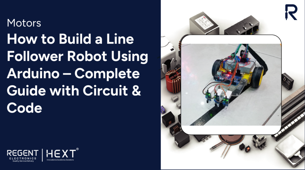
How to Build a Line Follower Robot Using Arduino – Complete Guide with Circuit & Code
A line follower robot is an autonomous vehicle designed to follow a visible path, typically a black line on a white surface or vice versa. These robots are widely used in academic projects and industrial automation for tasks like material handling and logistics.
In this tutorial by Regent Electronics, we’ll walk you through how to build your own line follower robot using Arduino, IR sensors, and basic electronic components.
What Is a Line Follower Robot?
A line follower robot follows a predefined path marked on the floor. It uses infrared (IR) sensors to detect the line and sends input to the Arduino, which then controls the direction and speed of the motors accordingly.
These types of robots are commonly used in:
- Educational STEM kits
- Industrial automation
- Delivery and service robotics
- Military and rescue operations
How It Works
The working principle of a line follower robot is based on the light reflection properties of surfaces:
- White surfaces reflect infrared light.
- Black surfaces absorb infrared light.
Using IR Sensors:
Each IR sensor module consists of an IR LED (emitter) and a photodiode (receiver). When the IR light reflects off a white surface, the photodiode detects the reflection and sends a signal to the Arduino. If the surface is black, no reflection occurs, and the sensor reads a different signal level.
Based on these readings, the Arduino adjusts the robot’s movement by controlling the motors via a motor driver.
Components Required
Here’s a complete list of components you’ll need to build your line follower robot:
- Arduino Uno (ATmega328P-based board)
- IR Sensor Module (2x)
- L298N Motor Driver Module
- BO (Battery-Operated) Motors (4x, single-shaft)
- Wheels (4x)
- Lithium-Ion Battery (2x, 3.7V connected in series)
- Robot Chassis or DIY base (cardboard works!)
- Jumper Wires
Brief Overview of Key Components
Arduino Uno
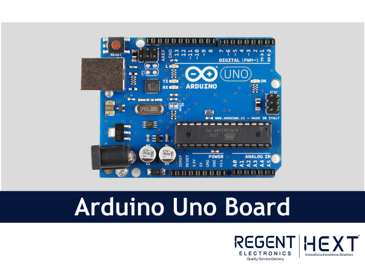
The Arduino Uno is the brain of the robot. It reads sensor inputs and drives the motors accordingly. It features 14 digital I/O pins and 6 analog input pins, and can be powered via USB or an external battery (7V–12V recommended).
IR Sensor
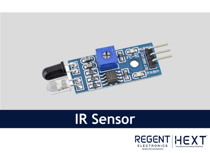
An IR sensor emits and detects infrared light. It senses whether the surface underneath is black or white and sends this data to the Arduino for processing.
L298N Motor Driver
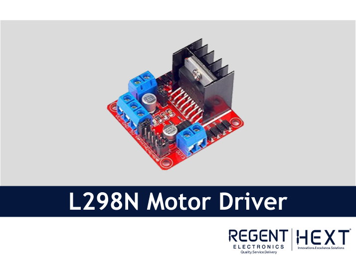
This dual H-Bridge motor driver allows independent control of two DC motors. It supports speed and direction control using ENA/ENB (enable) and IN1–IN4 (input) pins.
BO Motors
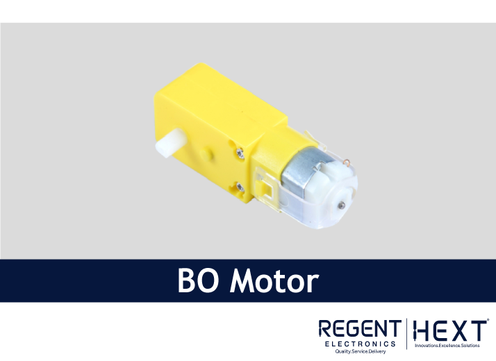
These compact, low-power DC motors are ideal for small robot projects. They offer a good balance between torque and RPM.
Lithium-Ion Battery
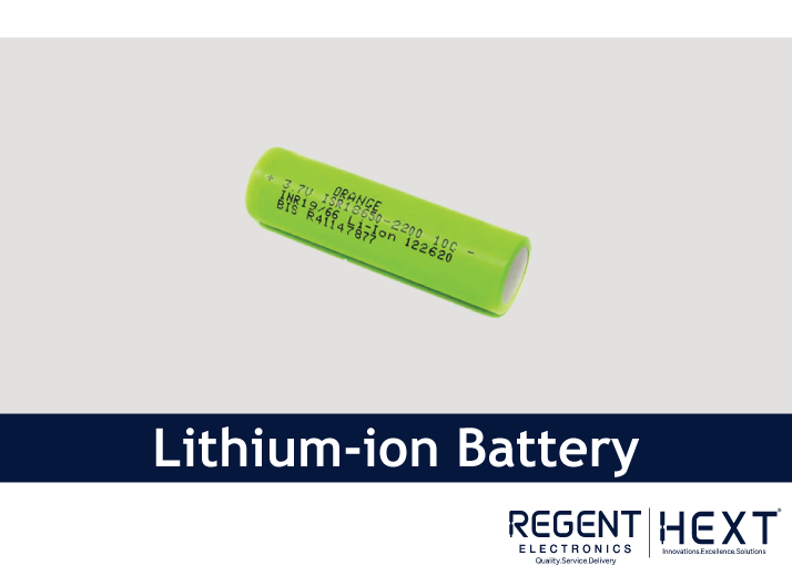
Two 3.7V lithium-ion batteries connected in series provide a total of 7.4V to 8.4V, enough to power the entire robot.
Circuit Diagram & Connections
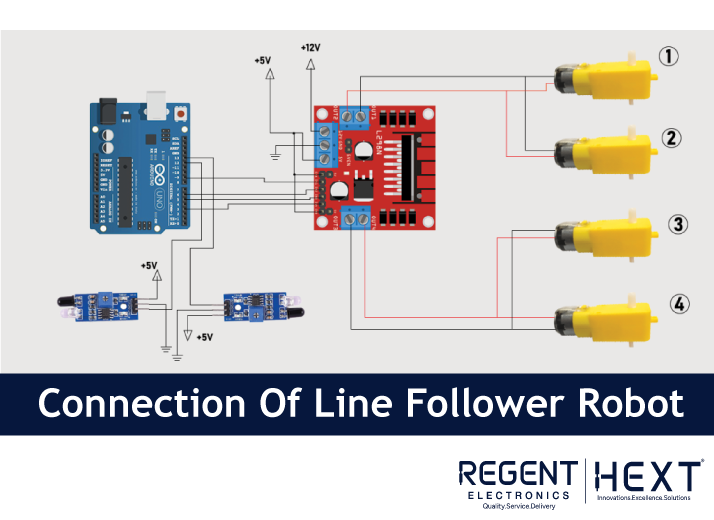
- Motor A (Left Side): Connect to OUT1 and OUT2 of the L298N
- Motor B (Right Side): Connect to OUT3 and OUT4 of the L298N
- L298N Input Pins:
- IN1 → Arduino Pin 9
- IN2 → Arduino Pin 6
- IN3 → Arduino Pin 5
- IN4 → Arduino Pin 3
- IR Sensors:
- Left Sensor → Arduino Pin 13
- Right Sensor → Arduino Pin 12
- Use jumpers between ENA/ENB and 5V on the motor driver to enable speed control.
🔧 Tip: If your robot doesn’t move straight, adjust motor polarity or IR sensor alignment.
Arduino Code for Line Follower Robot
Upload this code to your Arduino Uno using the Arduino IDE:
cpp
CopyEdit
int mot1=9;
int mot2=6;
int mot3=5;
int mot4=3;
int left=13;
int right=12;
int Left=0;
int Right=0;
void LEFT(void);
void RIGHT(void);
void STOP(void);
void setup() {
pinMode(mot1, OUTPUT);
pinMode(mot2, OUTPUT);
pinMode(mot3, OUTPUT);
pinMode(mot4, OUTPUT);
pinMode(left, INPUT);
pinMode(right, INPUT);
digitalWrite(left, HIGH);
digitalWrite(right, HIGH);
}
void loop() {
analogWrite(mot1, 255);
analogWrite(mot2, 0);
analogWrite(mot3, 255);
analogWrite(mot4, 0);
while(1) {
Left = digitalRead(left);
Right = digitalRead(right);
if (Left == 0 && Right == 1) LEFT();
else if (Right == 0 && Left == 1) RIGHT();
}
}
void LEFT(void) {
analogWrite(mot3, 0);
analogWrite(mot4, 30);
while (Left == 0) {
Left = digitalRead(left);
Right = digitalRead(right);
if (Right == 0) {
STOP();
while (Left == 0 && Right == 0) {
Left = digitalRead(left);
Right = digitalRead(right);
}
}
analogWrite(mot1, 255);
analogWrite(mot2, 0);
}
analogWrite(mot3, 255);
analogWrite(mot4, 0);
}
void RIGHT(void) {
analogWrite(mot1, 0);
analogWrite(mot2, 30);
while (Right == 0) {
Left = digitalRead(left);
Right = digitalRead(right);
if (Left == 0) {
STOP();
while (Left == 0 && Right == 0) {
Left = digitalRead(left);
Right = digitalRead(right);
}
}
analogWrite(mot3, 255);
analogWrite(mot4, 0);
}
analogWrite(mot1, 255);
analogWrite(mot2, 0);
}
void STOP(void) {
analogWrite(mot1, 0);
analogWrite(mot2, 0);
analogWrite(mot3, 0);
analogWrite(mot4, 0);
}
Final Testing & Calibration
Once your code is uploaded:
- Place your robot on a white surface with a clear black path.
- If it doesn’t follow the line properly, adjust:
- IR sensor positions
- Potentiometers on the IR modules
- Motor wiring if direction is reversed
Conclusion

That’s it! You’ve successfully built a basic line follower robot using Arduino. This is a great entry point for robotics enthusiasts and students looking to understand automation and embedded systems.
Stay tuned with Regent Electronics for more DIY electronics tutorials, robotics kits, and sensor-based projects. Whether you’re a hobbyist or educator, our step-by-step guides help bring your ideas to life!