

Blinking LED Using GPIO Pins of Raspberry Pi
Introduction
This guide will walk you through the process of blinking an LED using the GPIO pins of a Raspberry Pi. This is a fundamental project that helps you understand how to control electronic components using Raspberry Pi’s GPIO (General Purpose Input Output) pins.
Understanding Raspberry Pi GPIO Pins
The Raspberry Pi 3 B+ features a total of 40 GPIO pins. Below is a brief explanation of their configuration:
Pin Configuration Overview
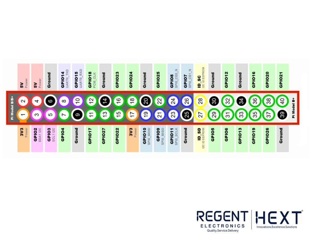
- Voltage Pins: Two 5V (pins 2 and 4) and two 3.3V (pins 1 and 17) pins.
- Ground Pins: Multiple ground (0V) pins available (pins 6, 9, 14, 20, 25, 30, 34, and 39), which are unconfigurable.
- General-Purpose Pins: All other pins are 3.3V, meaning they can be used for both input and output.
- Outputs: A GPIO pin set as an output can be toggled between HIGH (3.3V) and LOW (0V).
- Inputs: A GPIO pin set as an input reads either HIGH (3.3V) or LOW (0V).
- Special Functions: Some GPIO pins support additional functionalities such as:
- PWM (Pulse-Width Modulation): GPIO12, GPIO13, GPIO18, GPIO19.
- SPI (Serial Peripheral Interface): Used for communication with other hardware.
- I2C (Inter-Integrated Circuit): GPIO2 (SDA) and GPIO3 (SCL) for data transmission.
- UART (Universal Asynchronous Receiver/Transmitter): GPIO14 (TX) and GPIO15 (RX).
For a detailed pin layout, you can visit Raspberry Pi Pinout.
Blinking LED Using a GPIO Pin
Step 1: Components Required
- Raspberry Pi (any model with GPIO support)
- 1 LED
- 1 Resistor (270Ω, 330Ω, or 1kΩ)
- Jumper Wires
- Breadboard
Step 2: Connections
We will be using GPIO 21 (Pin 40) to control the LED and Ground (Pin 39) to complete the circuit.
- Connect the anode (+) of the LED to GPIO 21 (Pin 40) via a current-limiting resistor.
- Connect the cathode (-) of the LED to Ground (Pin 39).
Step 3: Writing the Python Code

- Open Python 3 (IDLE) on your Raspberry Pi.
- Create a new Python script and name it blink.py.
- Copy and paste the following code:
import RPi.GPIO as GPIO # Import GPIO library
import time # Import time library
LedPin = 40 # Define LED pin (GPIO 21 – Pin 40)
def setup():
GPIO.setmode(GPIO.BOARD) # Use physical pin numbering
GPIO.setup(LedPin, GPIO.OUT) # Set LED pin as output
GPIO.output(LedPin, GPIO.HIGH) # Turn LED on initially
def blink():
while True:
GPIO.output(LedPin, GPIO.HIGH) # LED ON
time.sleep(1) # Wait 1 second
GPIO.output(LedPin, GPIO.LOW) # LED OFF
time.sleep(1) # Wait 1 second
def destroy():
GPIO.output(LedPin, GPIO.LOW) # Turn LED off
GPIO.cleanup() # Release GPIO resources
if __name__ == ‘__main__’:
setup()
try:
blink()
except KeyboardInterrupt: # Stop program with Ctrl+C
destroy()
Step 4: Running the Code
- Save the file as blink.py.
- Open the terminal and navigate to the file’s directory.
- Run the following command:
sudo python blink.py
- Press Ctrl+C to stop the script.
Conclusion
You have successfully learned how to blink an LED using Raspberry Pi’s GPIO pins. This simple project lays the foundation for more complex electronic projects, such as sensor integration and automation systems. If you have any questions or suggestions, feel free to leave a comment!
Stay tuned for more Raspberry Pi tutorials from Regent Electronics! 🚀