
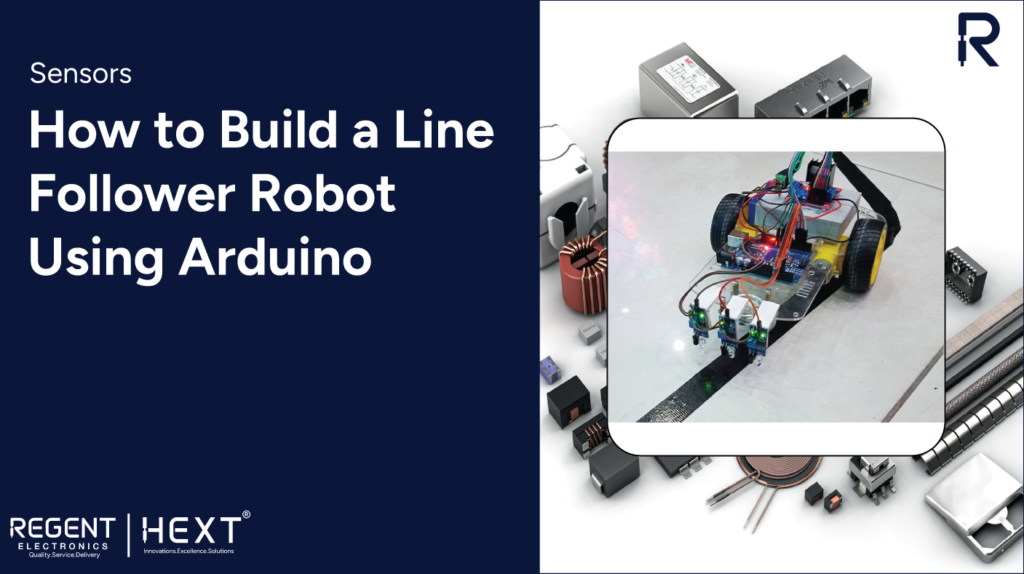
How to Build a Line Follower Robot Using Arduino – Connection & Code
Introduction
A line follower robot is an autonomous vehicle designed to follow a predefined path, usually a black line on a white surface or vice versa. This type of robot is widely used in industrial automation, delivery services, and even military applications. In this article, we will explore how to create a line follower robot using Arduino, including its working principle, components, connections, and code.
Working Principle of a Line Follower Robot
The fundamental concept behind a line follower robot revolves around light behavior on different surfaces. A white surface reflects light, while a black surface absorbs it. The robot employs infrared (IR) sensors to detect these light variations and send corresponding signals to the Arduino. The Arduino processes these signals and controls the motors accordingly to keep the robot on track.
Components Required
To build a line follower robot, you will need the following components:
- Arduino Uno – Microcontroller board for processing signals.
- IR Sensors – To detect the line.
- L298N Motor Driver – Controls the speed and direction of motors.
- BO Motors – Small DC motors to drive the robot.
- Wheels – For mobility.
- Lithium-Ion Battery – Power source.
- Jumper Wires – For wiring connections.
- Robot Chassis – Optional frame to hold components (can be made from cardboard or plastic).
Understanding the Components
Arduino Uno
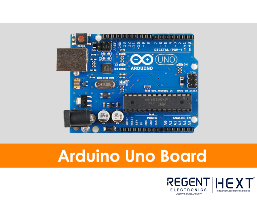
The Arduino Uno is a microcontroller board featuring the ATmega328P chip. It provides 14 digital I/O pins (6 of which support PWM) and 6 analog input pins. It is programmed using the Arduino IDE via a USB cable.
Infrared Sensor
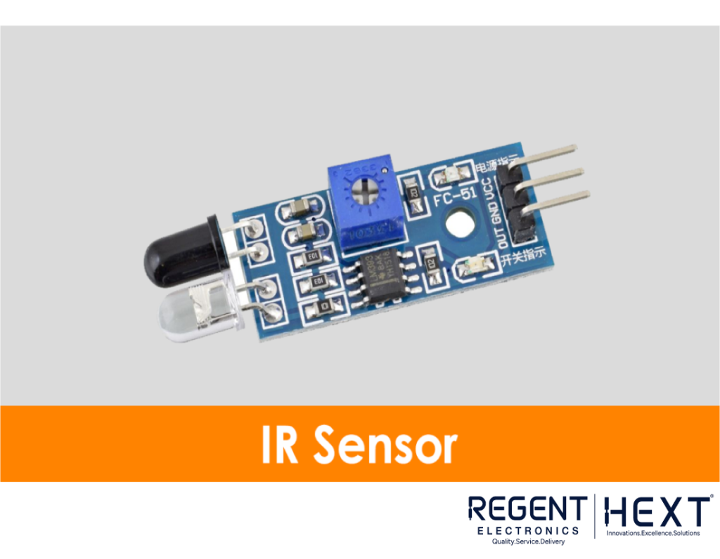
The IR sensor consists of an IR LED (emitter) and an IR photodiode (receiver). The emitter sends infrared rays, and the receiver detects reflections from surfaces. A white surface reflects IR light, whereas a black surface absorbs it, causing a change in voltage that the Arduino reads.
L298N Motor Driver
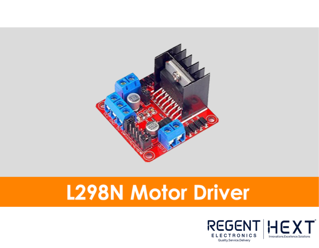
The L298N is a dual H-Bridge motor driver module that enables independent control of two DC motors. It has speed control pins (ENA, ENB) and direction control pins (IN1, IN2, IN3, IN4), which are connected to the Arduino.
BO Motors
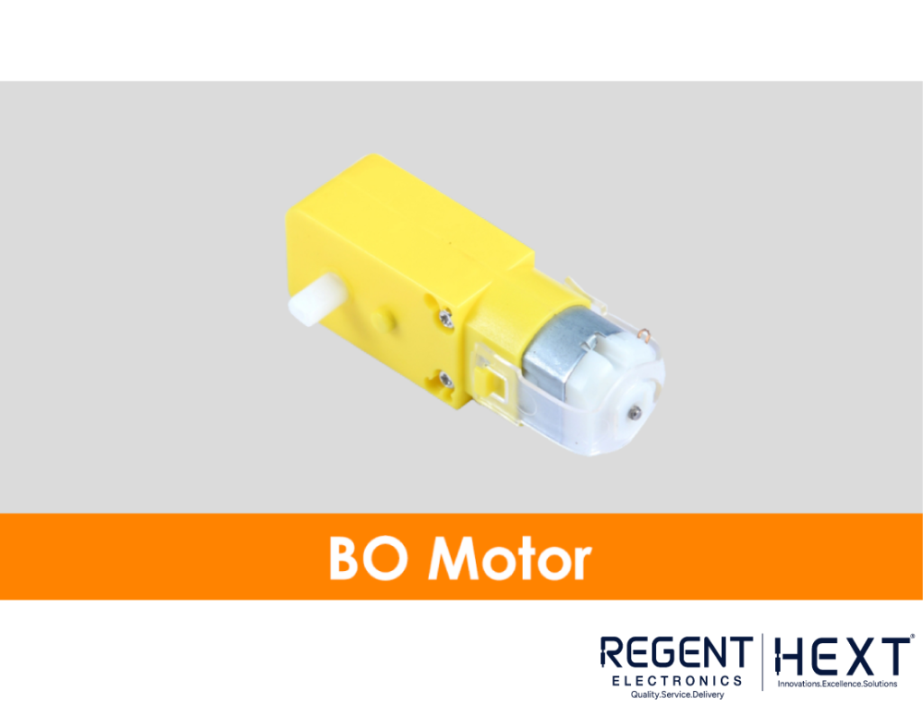
Battery-operated (BO) motors are compact DC motors ideal for robotics applications. They provide decent torque and speed while consuming minimal power.
Lithium-Ion Battery
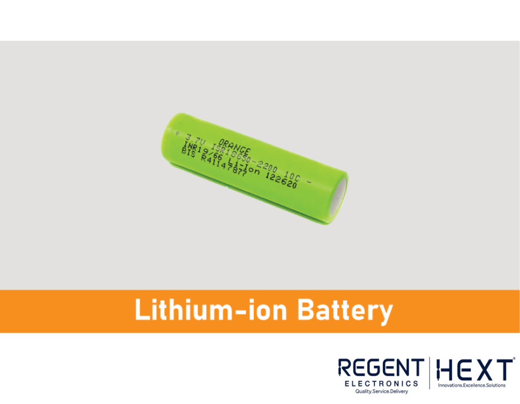
A lithium-ion battery supplies power to the Arduino and motors. Two batteries connected in series provide an output voltage of 8.4V when fully charged.
Wiring & Connection Diagram
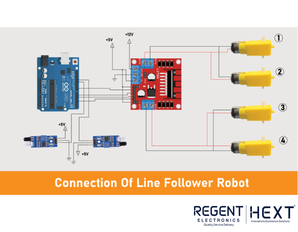
The robot uses four BO motors, where:
- Motors 1 and 2 are connected to channel 1 of the L298N driver.
- Motors 3 and 4 are connected to channel 2 of the L298N driver.
- The ENA and ENB pins control motor speed.
- IN1, IN2, IN3, and IN4 pins are connected to Arduino pins 9, 6, 5, and 3.
The IR sensors are positioned at the front to detect the path. The Arduino processes sensor inputs and controls the motors accordingly.
Arduino Code
Download the Arduino IDE and upload the following code to your board:
int mot1 = 9;
int mot2 = 6;
int mot3 = 5;
int mot4 = 3;
int left = 13;
int right = 12;
int Left = 0;
int Right = 0;
void LEFT (void);
void RIGHT (void);
void STOP (void);
void setup()
{
pinMode(mot1, OUTPUT);
pinMode(mot2, OUTPUT);
pinMode(mot3, OUTPUT);
pinMode(mot4, OUTPUT);
pinMode(left, INPUT);
pinMode(right, INPUT);
digitalWrite(left, HIGH);
digitalWrite(right, HIGH);
}
void loop()
{
analogWrite(mot1, 255);
analogWrite(mot2, 0);
analogWrite(mot3, 255);
analogWrite(mot4, 0);
while(1)
{
Left = digitalRead(left);
Right = digitalRead(right);
if ((Left == 0 && Right == 1) == 1)
LEFT();
else if ((Right == 0 && Left == 1) == 1)
RIGHT();
}
}
void LEFT (void)
{
analogWrite(mot3, 0);
analogWrite(mot4, 30);
while(Left == 0)
{
Left = digitalRead(left);
Right = digitalRead(right);
if (Right == 0)
{
STOP();
}
analogWrite(mot1, 255);
analogWrite(mot2, 0);
}
analogWrite(mot3, 255);
analogWrite(mot4, 0);
}
void RIGHT (void)
{
analogWrite(mot1, 0);
analogWrite(mot2, 30);
while(Right == 0)
{
Left = digitalRead(left);
Right = digitalRead(right);
if (Left == 0)
{
STOP();
}
analogWrite(mot3, 255);
analogWrite(mot4, 0);
}
analogWrite(mot1, 255);
analogWrite(mot2, 0);
}
void STOP (void)
{
analogWrite(mot1, 0);
analogWrite(mot2, 0);
analogWrite(mot3, 0);
analogWrite(mot4, 0);
}
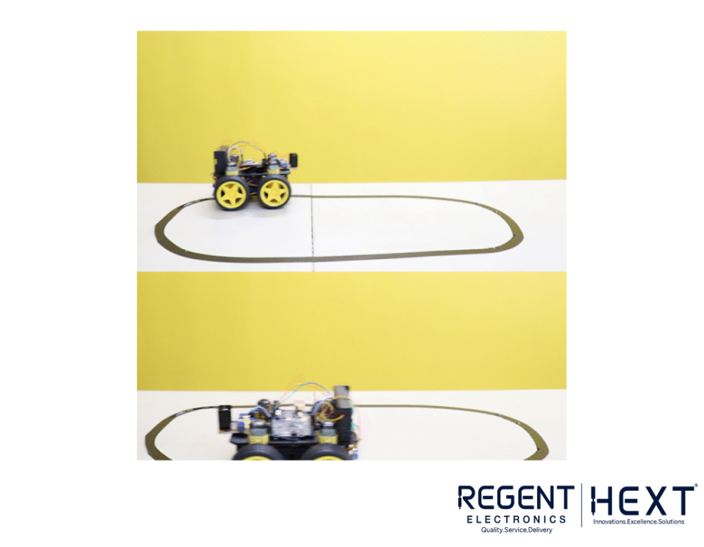
Testing the Line Follower Robot
After uploading the code, check if your robot follows the line correctly. If it moves in the wrong direction, reverse the wiring of the BO motors. Adjust the IR sensor sensitivity using its onboard potentiometer.
The robot should follow a black path on a white surface. You can draw a track using black tape on a white sheet.
Conclusion
Building a line follower robot is a great beginner-friendly project that introduces fundamental robotics and automation concepts. This robot can be expanded by integrating obstacle avoidance, speed control, and wireless communication for advanced applications.
We hope this guide helps you build your own line follower robot. Have fun experimenting and enhancing your robotic skills! 🚀