
Interfacing Hall Effect Sensor with Arduino – Connection & Code
Introduction In this article, we will explore the working principle of the Hall Effect sensor, how to interface it with an Arduino, and the necessary code implementation.
Understanding the Hall Effect Sensor
Hall Effect sensors operate based on magnetic field detection. These sensors function by responding to the behavior of charge carriers when subjected to electricity and magnetic fields. This principle extends from the Lorentz Force.
Hall Effect sensors are widely used in various applications such as wheel speed detection, switches, position sensing, and many more.
How Does a Hall Effect Sensor Work?

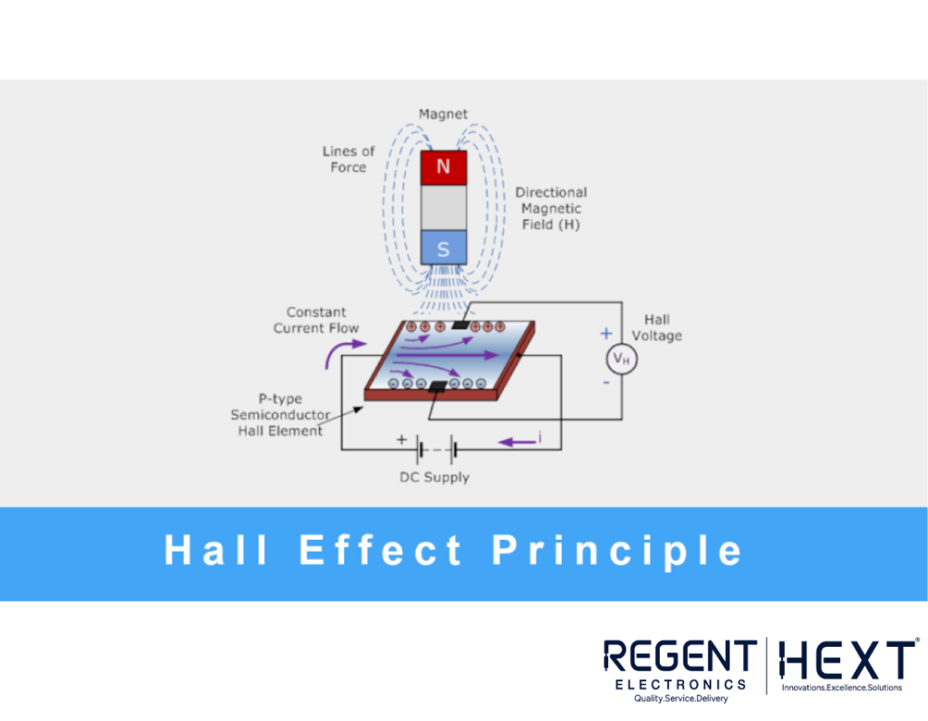
Hall Effect sensors are activated by an external magnetic field. A magnetic field has two essential characteristics: flux (B) and polarity (North and South Poles). The sensor’s output depends on the field density around it. When the magnetic density exceeds a certain threshold, the sensor generates an output voltage known as the Hall Voltage (VH).
These sensors typically consist of a thin rectangular piece of semiconductor material like gallium arsenide (GaAs), indium antimonide (InSb), or indium arsenide (InAs), which allows a constant current to pass through it. When exposed to a magnetic flux, the charge carriers (electrons and holes) in the semiconductor material shift to either side, creating a potential difference.
For the Hall Effect to generate a voltage, the magnetic flux lines must be perpendicular (90°) to the current flow and have the correct polarity, usually a south pole. Hall Effect sensors provide data about the type and strength of the magnetic field. Generally, these sensors remain “OFF” (open circuit) in the absence of a magnetic field and switch “ON” (closed circuit) when exposed to a sufficiently strong magnetic field.
Interfacing a Hall Effect Sensor with Arduino
Once you have your hardware and code ready, upload the code to the Arduino. You can use a 9V battery or any other suitable power source. Connect the sensor to the motor as shown in the diagram.
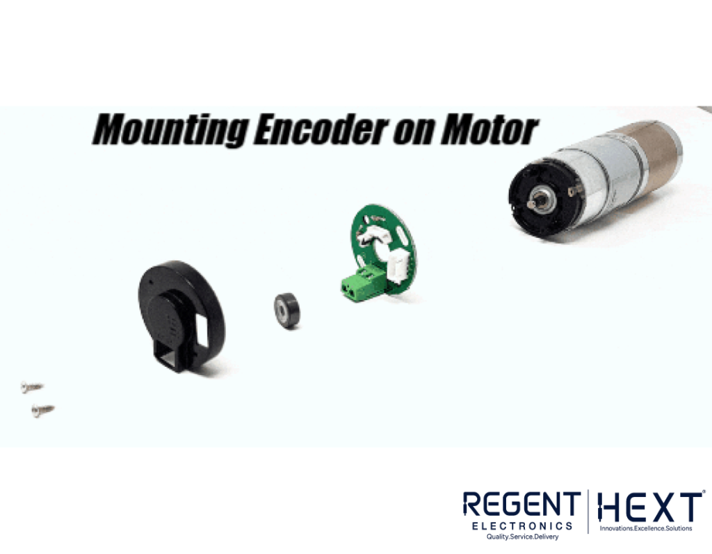
Mounting the Encoder on the Motor
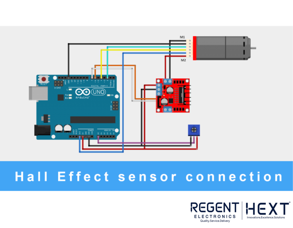
Secure the sensor properly onto the motor and connect its wires to the Arduino. We will be using an L298N motor driver, as shown in the connection diagram below.
Once the setup is complete, upload the following code to the Arduino:
Code Implementation
// Program: Motor DC with Encoder
const byte Encoder_C1 = 2;
const byte Encoder_C2 = 4;
byte Encoder_C1Last;
int duration;
boolean direction;
// Motor driver L298N pins
#define motor_pin1 6
#define motor_pin2 7
void setup() {
Serial.begin(57600);
pinMode(A0, INPUT);
pinMode(motor_pin1, OUTPUT);
pinMode(motor_pin2, OUTPUT);
EncoderInit();
}
void loop() {
Serial.print(“Pulse: “);
Serial.print(duration);
int value = analogRead(A0);
if (value >= 512) {
digitalWrite(motor_pin1, LOW);
digitalWrite(motor_pin2, HIGH);
Serial.println(“Anti-clockwise”);
} else {
digitalWrite(motor_pin1, HIGH);
digitalWrite(motor_pin2, LOW);
Serial.println(“Clockwise”);
}
duration = 0;
delay(100);
}
void EncoderInit() {
pinMode(Encoder_C2, INPUT);
attachInterrupt(0, calculatePulse, CHANGE);
}
void calculatePulse() {
int Lstate = digitalRead(Encoder_C1);
if ((Encoder_C1Last == LOW) && Lstate == HIGH) {
int val = digitalRead(Encoder_C2);
direction = (val == HIGH) ? true : false;
}
Encoder_C1Last = Lstate;
duration += (direction) ? -1 : 1;
}
Final Thoughts
In this article, we covered the working principle of the Hall Effect sensor, how to interface it with an Arduino, and the implementation of code for practical applications.
By following these steps, you can successfully use a Hall Effect sensor with Arduino for various automation and robotics projects. We hope this guide helped you learn something new. Stay tuned for more tutorials!
Regent Electronics – Innovating for the Future!